B-4.4 Distribution System Installation
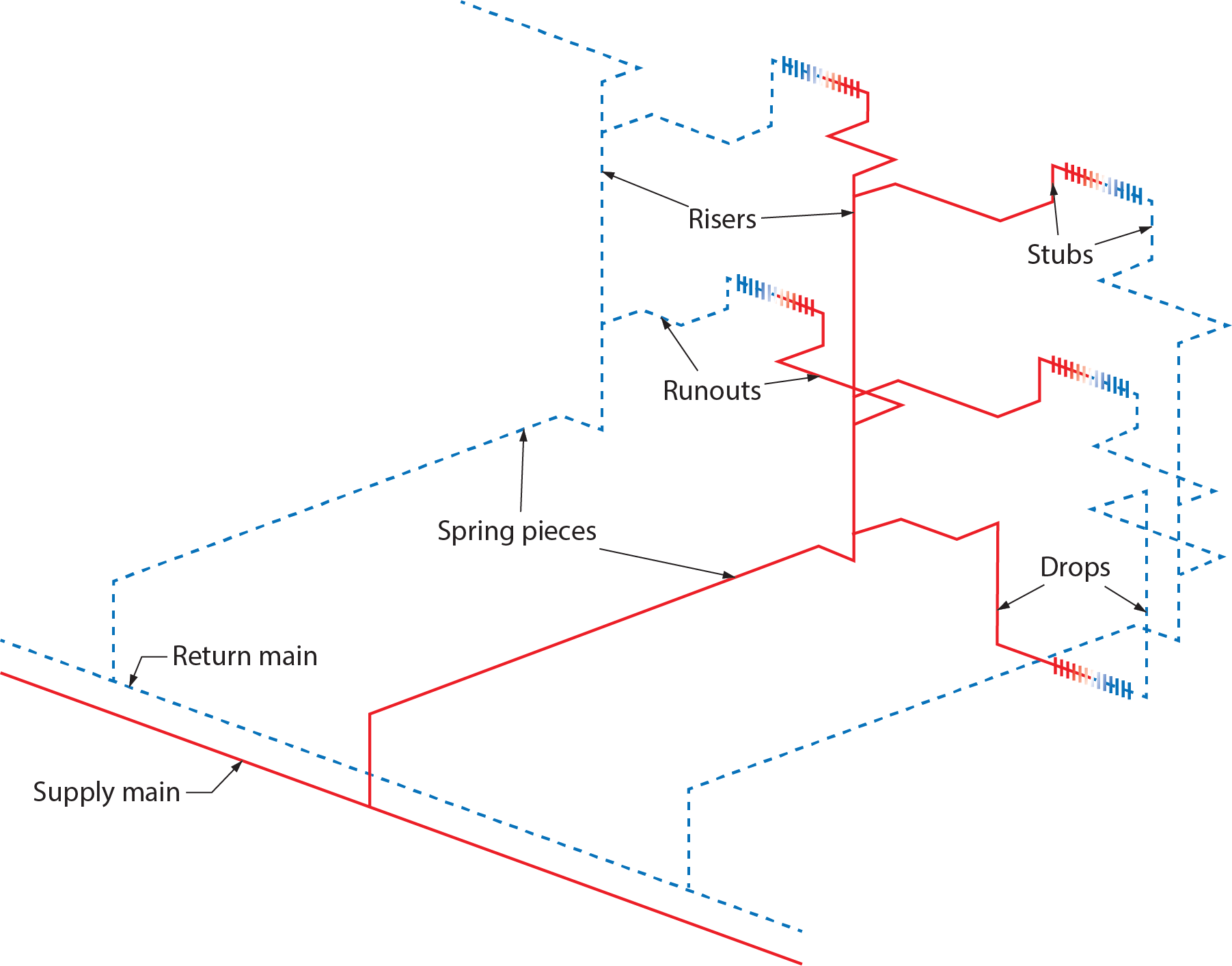
As mentioned earlier, piping layouts are categorized by the configuration of the supply and return mains. Piping branches, also called runouts, connect the mains to the heat transfer units through drops, stubs, and spring pieces. All of these terms lack clear-cut definitions that relate to their sizing, in contrast to the definitions of piping in drainage, waste, and venting systems. Mains, risers, and branches are all sized according to the amount of heat they need to transport.
Regardless of the names describing the parts of a hydronic system, piping must be designed to prevent air blockages within the system. The correct installation of piping must also prevent the buildup of stress that would cause damage and leaks.
Parts of the Distribution System
The following terms identify pipes in hydronic systems:
- Supply main
- Return main
- Branch or spring piece
- Riser
- Runout
- Stub
- Drop
Supply and Return Mains
The supply and return mains are typically attached to the boiler in all systems except primary/ secondary and carry all of the system water to the other pipes. In larger buildings, the supply and return mains are usually run down a hallway, while the heat transfer units are positioned along the outside walls. This pattern is repeated on every storey.
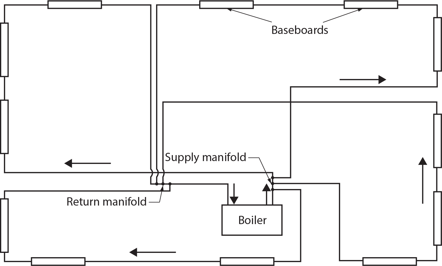
Figure 1 shows piping connected to supply and return mains. Note that the spring pieces are installed to minimize the effects of expansion and contraction of the piping and are classified as branches.
Branches, Spring Pieces, and Risers
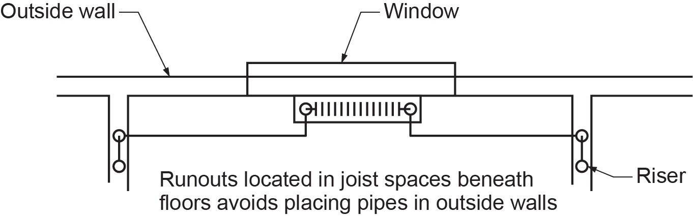
A branch in piping is simply a pipe connected to a main, much the same as a branch of a tree is connected to the trunk of the tree. Branches connect the heat transfer units to the mains via drops and stubs. A spring piece is a branch that connects a main to a riser. A riser runs vertically to the highest floor in the building and is usually located within an interior wall near the outside wall. This keeps the riser within the heating portion of the building, preventing freezing. The distance from this location to the heat transfer units is normally kept fairly short. Figure 2 shows the location of the riser.
Piping branches must be designed to prevent the buildup of stress through thermal expansion and contraction as well as to prevent air blockages within the pipes. Risers must be protected from stresses caused by thermal expansion, building shrinkage, and settlement.
Runouts
A runout is a horizontal pipe that connects the heat transfer unit to a riser or main. Runouts may connect directly to the heat transfer unit or by way of a stub or drop. Runouts may also form a series loop along the outside wall. Runouts on outside walls are usually installed below the floor, between the floor joists, which prevents them from freezing. Figure 2 shows how runouts are installed with respect to an outside wall.
Stubs and Drops
A stub is a short vertical pipe connected to a runout that passes up through a floor to a heat transfer unit. A drop runs down from a runout to a heat transfer unit.
Thermal Expansion and Other Forces
Pipes and connections can crack and leak if subjected to severe stresses. These stresses are created by thermal expansion and other forces that make a component move with respect to others. Allowance must be made for these movements to minimize these stresses.
All materials expand when heated. This is called thermal expansion. As a pipe becomes warmer, it becomes longer. When water in a 30 m (100’) steel pipe is heated from its fill temperature of approximately 10°C (50°F) to operating temperature of 82°C (180°F), the pipe will become 25 mm (1 in.) longer. Copper tubes expand at a similar rate, and plastic tubes expand even more. Boilers, heat transfer units, and other components are also affected by thermal expansion, but these components are stationary, so they cannot be modified.
Other forces that cause stress in a hot-water piping system are fluid surges, pipe misalignments, impacts, and movements during an earthquake. The buildup of stress through thermal expansion and other forces is prevented using:
- Swing joints
- Expansion loops
- Expansion bellows
- Oversized holes through building structures
Swing Joints
Swing joints, such as spring pieces (Figure 3), are used to conveniently install piping that allows for stresses and for grade. Making a swing joint involves adding three or more elbows and connecting pipes to a piping run. The changes in direction created by the swing joint provide offsets that can move without breaking as pipes expand and contract.
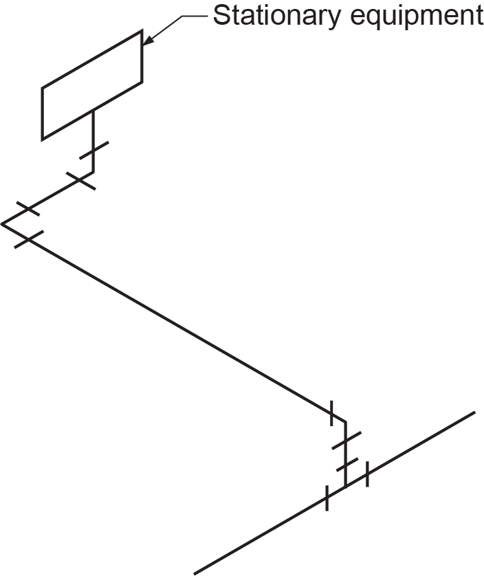
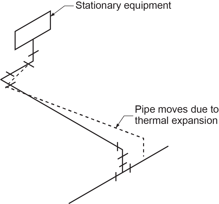
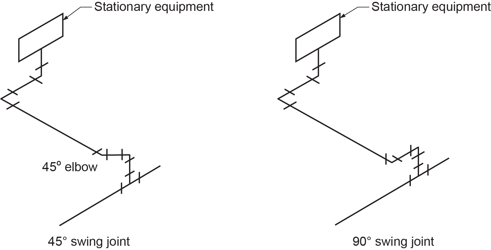
Figure 4 shows how a swing joint reacts to thermal expansion. The stub is rigidly fixed to the supply main. As the water in the supply main becomes warmer, the supply main expands so the stub moves in the direction of flow. The offset to the stationary component allows enough motion to prevent significant stress. The movement of swing joints responds to other forces as well.
Ease of Installation
Swing joints make installation and repair easier and leaks less likely. Swing joints make it easier to install a pipe with grade for draining and air elimination and easier to align fittings. For threaded pipe installations, alignment of threaded connections is less difficult if the installer is able to use an extra fitting to take up slight misalignments. A tee in a main is often not well positioned for good alignment. Turning the tee on the main would loosen one side and possibly cause a leak, but an extra elbow installed at the main would allow easy alignment and hook-up.
The elbows in swing joints can be 90° elbows or a combination of 45° and 90° elbows. Figure 5 shows the differences between 45° and 90° swing joint configurations.
Expansion Loops
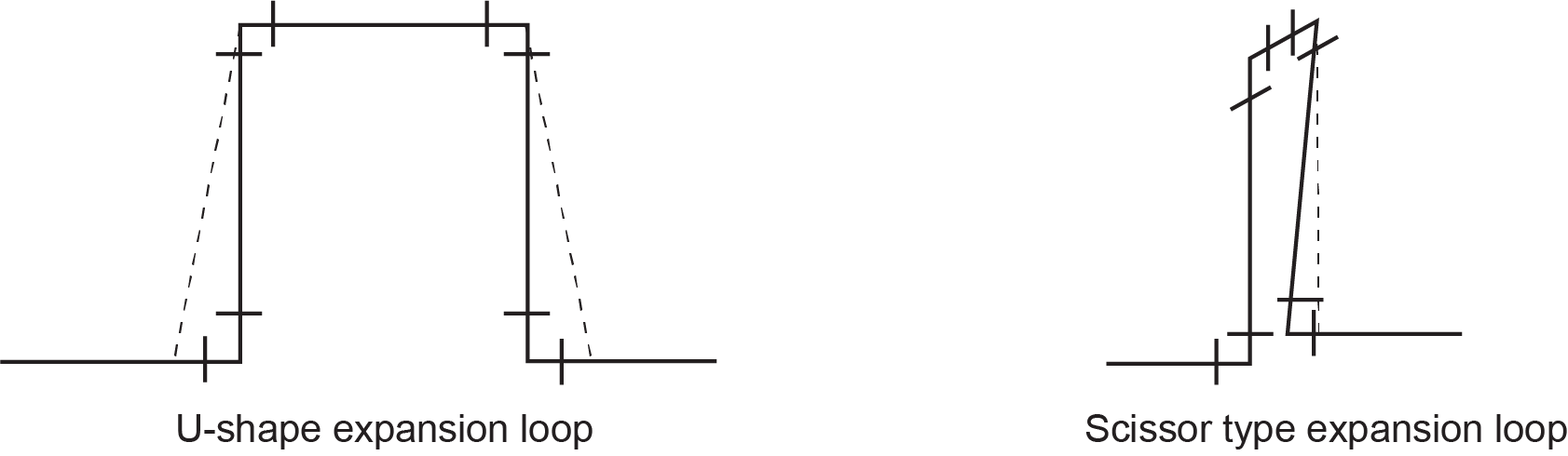
Expansion loops are a variation of a swing joint. Expansion loops allow a pipe to change in length as parts of the loop twist or bend. An expansion loop may be either U-shaped or scissor type (Figure 6). Expansion loops are most commonly used on long mains.
Expansion Bellows
An expansion bellows has the same function as an expansion loop. However, the expansion bellows is made of materials, such as reinforced butyl rubber or corrugated metal, that collapses like an accordion when adjoining pipes expand. In other words, the expansion bellows becomes shorter as the pipes become longer and are much more compact than expansion loops.
Oversized Holes Through Building Structures
There must be room for pipe movement in any hole a pipe goes through. In some jurisdictions, the size of the holes is also specified by local seismic codes. For commercial applications, specific requirements for installation will be detailed by the mechanical engineer in the drawings and specifications. For instance, a 3 m (10 ft) horizontal pipe will expand 2.5 mm ([latex]\tfrac{1}{8}[/latex] in.) through its operating temperature range. If this pipe is connected to two vertical pipes that pass through a floor, the vertical pipes will move away from one another by 2.5 mm.
Pipes will expand in diameter as well as in length. To allow for both directions of expansion, drill all holes a minimum of 12 mm ([latex]\tfrac{1}{2}[/latex] in.) larger than the size of the pipe. After installing the pipe, seal the hole to prevent air leaks and create fire stops. Grommets or silicone caulk will seal the hole but still allow the pipe to expand and contract.
Prevention of Air Blockage
The installation of piping requires paying attention to more than just the prevention of stress caused by thermal expansion and contraction. Of equal importance is the control of air within the system. Pockets of air can cause a reduction in the transfer of heat as well as no heat transfer at all. Installing piping correctly will help to minimize or eliminate problems caused by the accumulation of air within the system piping.
Air blockage is prevented using:
- Correct grade on piping
- Vent tees at high points
Grade
Air blockages are prevented by installing some grade (slope) to piping runs. Horizontal runs must grade slightly upward in the direction of flow to allow air to move along with the heated water and reach an air vent. This grade can range from almost perfectly level to a rise of 4 mm/m (four millimetres per metre), which equates to roughly [latex]\tfrac{1}{2}[/latex] inch per 10 feet. The amount of grade will depend on the amount of space available and the ability to install swing joints to make up any misalignment caused by one pipe having grade and another not.
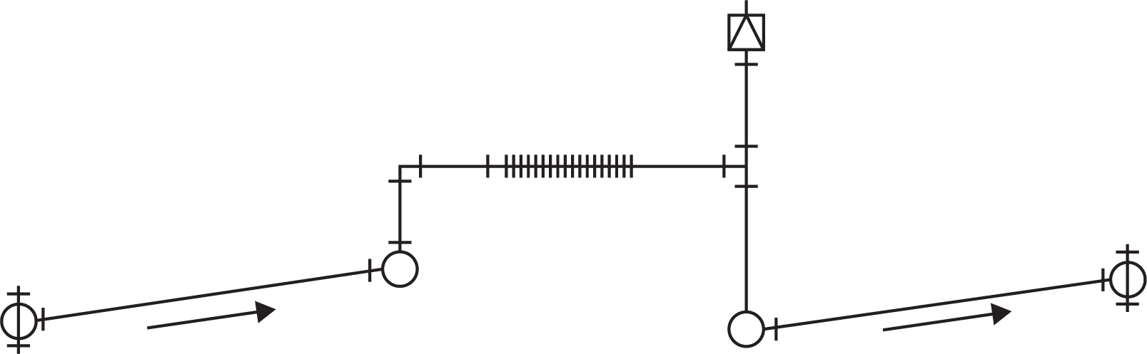
Although it is acceptable to install pipes in a level manner, it is advisable to install them with some grade so that air will be sure to clear the system. Figure 7 shows horizontal runouts that slope (exaggerated) upward, in the direction of flow, to vented high points.
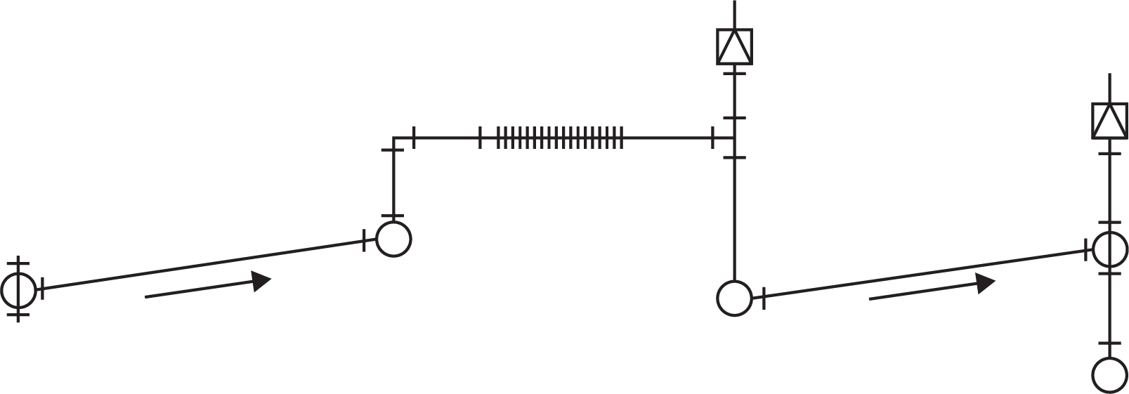
Air vents should be located at all high spots, where air will naturally accumulate. Occasionally, upward slope in the direction of horizontal flow involves the installation of an extra air vent. The extra air vent should be installed where it will be easily accessible, so that it can be serviced. Figure 8 shows the same runout as in Figure 7, but with an extra vent installed. If it appears that an air vent is going to be situated in an inaccessible area, do not install it there. Instead, run a vent pipe upward to an open area and install the vent there.
Pumps Cannot Clear Air Blockages
Air blockages cannot be overcome by the pressure or flow developed by a heating system circulator and should be avoided. A pump is designed to overcome the friction of the piping as it pushes the water through the heating system. Velocities in hot-water heating systems are far slower than when the heating system was initially purged, and therefore any air that accumulates at high points cannot be carried downward and to an air eliminator by a pump.
A heating system must be entirely full of water so that the pump is not required to lift the water, only to move it. All circuits of a hot-water heating system must have water flow to deliver heat. When there is an air blockage in a circuit, there is not enough pressure for the air to be forced through the system. Water flow is then redirected to other heating circuits not obstructed by air.
Zoning in a Hydronic System
A zone is a heating area controlled separately from other heating areas. Each zone is typically controlled by its own thermostat.
Installing zones in a hot-water heating system allows for:
- Greater comfort
- Lower operating cost
- Better temperature control in buildings with areas difficult to heat
Zoning makes a building more comfortable because it can provide each area with the amount of heat appropriate to its heat loss. Zoning saves money because not all areas require the same temperature (occupied as opposed to unoccupied) and because people are less likely to open windows if they are comfortable. Temperature control is possible in buildings with comfort challenges because every part of the building can be given a different piping or control strategy.
Selecting Zones
A hydronic system should be divided into zones if rooms or areas within the building have differences or similarities of factors, such as:
- Heat losses
- Orientation
- Occupancy
- Use patterns
- Floor constructions
- Glazing
The larger a building, the greater the need for zones.
Different Heat Losses
Every room or space will experience heat loss differently. To achieve the same temperature in every room, each room requires a different amount of heat. Installing one zone for every room enables the system to supply a required amount of heat to each room, although this will increase the cost of installation.
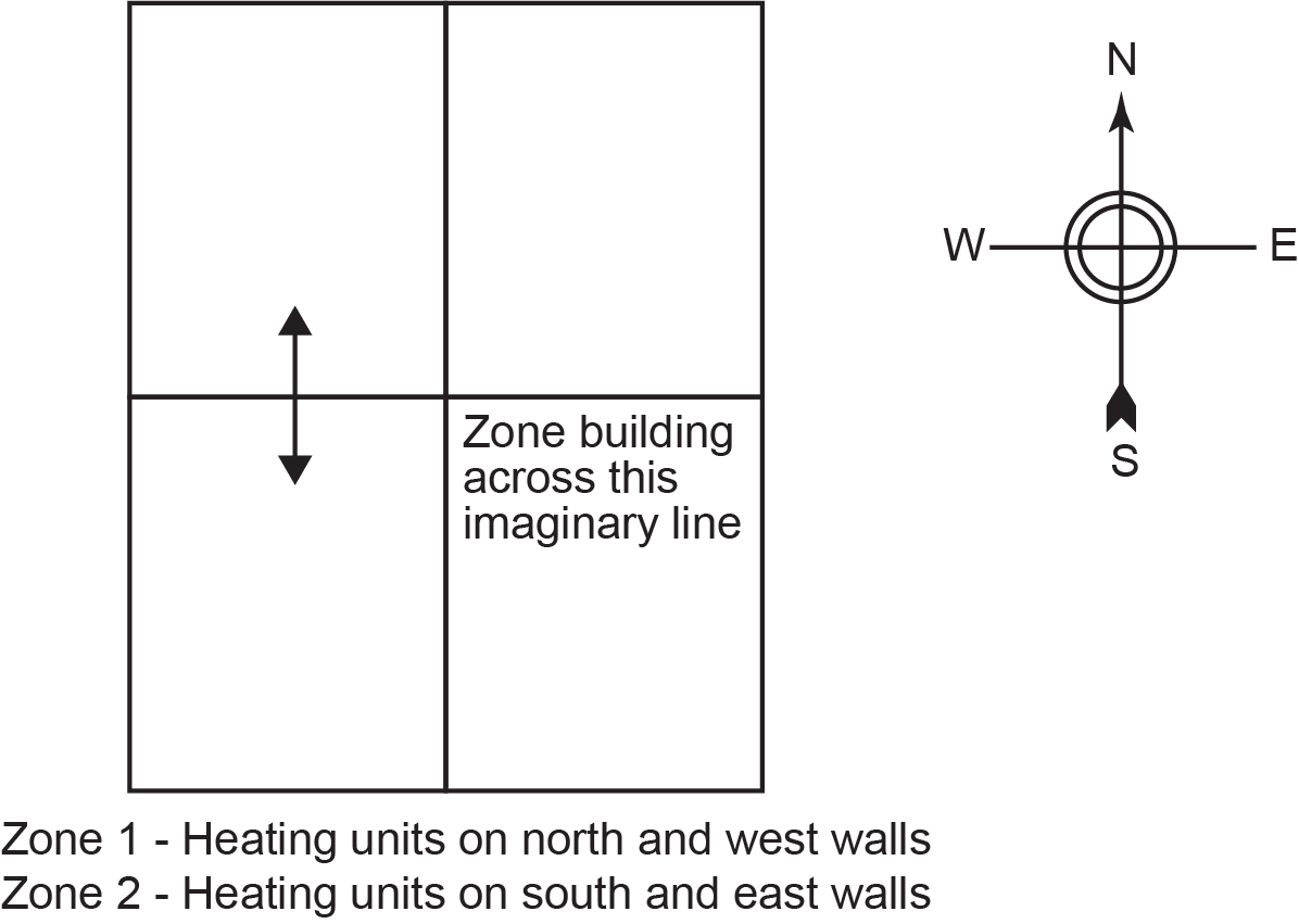
Orientation
The orientation of a building will determine on which sides the sun will influence the temperature of the rooms. Consider the square building in Figure 9. The rooms on the southeast receive heat from the sun in the morning. On the southwest side, however, the sun is not contributing heat, so heat is in greater demand. If the thermostat were in an east room, it would reduce the demand for heat in the morning, and the west room would be cold.
In the afternoon, the west room would receive heat from the sun and the east room would not. Since the thermostat is in the east room, it signals for high heat transfer, which makes the west room too hot. If the building were divided into four zones as shown in Figure 9, both these situations would be avoided. However, it is usually only necessary to use two zones because during the heating season, the sun rises in the southeast and sets in the southwest. Thus, more heat is needed in the cooler north side.
Occupancy
There is also a greater need for zoning in commercial buildings than in residential ones. An office worker, for instance, will not wish to spend much of their workday fussing with dampers on baseboard heaters, while homeowners are more likely to take on those type of issues. These days, large buildings are usually controlled by remote means. Occupants call, text, or email a building operator to relay information on the level of discomfort they are feeling, and the building operator can make adjustments from a computer, sometimes in a different city or province. Most commercial buildings no longer give the occupants control of the room thermostats. Thermostats have been replaced by remote sensors.
Use Patterns
The intended use of each area will influence the desired temperature. Infrequently used rooms should be separately zoned so they may be set at a lower temperature to conserve energy.
In a home, some rooms, such as a playroom or a work area, are used for high-energy activities. These activities will be more comfortable if the temperature is somewhat lower than normal. Other rooms will be used for low-energy activities, such as watching TV or eating. These activities will be more comfortable if the temperature is somewhat higher.
Sleeping is a low-energy activity, but bedrooms should generally be kept at a lower temperature because bedding provides the necessary comfort. The level of clothing worn varies with the room as well. Less clothing is worn in a bathroom than in a living room, and heat loss from a person who is wet after getting out of a shower or bathtub will be much higher than normal, so the temperature is usually kept higher.
Commercial buildings usually have one or two types of activity, such as shopping and office work. The energy level of the activity and the amount of clothing that people will wear should be considered when selecting zones.
Industrial buildings may require different heat zones. Industrial processes, such as agriculture, manufacturing, and warehousing, may require a particular temperature or number of air changes per hour. This makes proper zoning critical. These processes often produce waste heat, which must be calculated before zones can be selected.
Use patterns may change over the life of the building. Zones should be versatile enough to accommodate changes in use patterns. The installation of flow-balancing valves in each zone can help minimize the impact to the rest of the system by altering flow rates when changes in use occur.
Different Floor Constructions
If radiant floor panel heating is used, different floor constructions require different zones. Concrete and wood allow the passage of heat but at very different rates. The type of thermostat used for a concrete floor installation is different from that used for a wood floor installation. As a result, the same zone cannot include these two types of floor construction without proper design and planning.
Additional Heat Gains and Losses
Consider additional heat gains and losses when selecting zones. Additional heat gains result from activities, such as cooking or bathing, or from the operation of the boiler or other equipment. Additional losses result from frequently opened doors or windows. In commercial and industrial buildings, additional gains may result from industrial processes, lighting, operation of equipment, or occupants.
Most large commercial buildings will typically have a higher rate of heat gain than heat loss. Lighting, the people themselves, and especially computers emit much heat, so the cooling systems tend to have more work to do and are, therefore, larger than the heating systems.
Higher storeys of a building require less heat than lower storeys because of the stack effect. The stack effect refers to the movement of heat upward in a multi-storey building. The heat moves up elevator shafts and staircases and, to some extent, through the floors themselves.
The amount of heat gained through exposure to the sun is influenced by the orientation of the building, amount of window area, and amount of shade created by trees or roof eaves.
South-facing windows can contribute a significant amount of heat (solar gain). East- and west-facing windows may contribute some heat. North-facing windows cannot produce a heat gain regardless of their construction. Wide eaves and other objects, such as trees or other buildings, in close proximity can shade the window and reduce the amount of exposure to the sun.
Windows may have a heat gain when it is sunny, but they will always have a heat loss when there is no sun. The heat loss through windows is reduced if multi-glazed windows or insulating drapes are installed. The presence of a large window area increases the need for precise local zone control. The amount and type of glazing will minimally affect the heat loss in a residential home but will significantly affect the heat loss in a very large building.
Residential and Commercial Zones
In both residential and commercial hot-water heating systems, a zone is a primary division of the piping system. In a residential system, a zone is normally the smallest division, whereas in a commercial system, the zones are further divided into sub-zones.
In a residential system, using finned-tube baseboards, each zone is typically a one-pipe circuit that starts and ends near the boiler or manifold off of the supply and return mains.
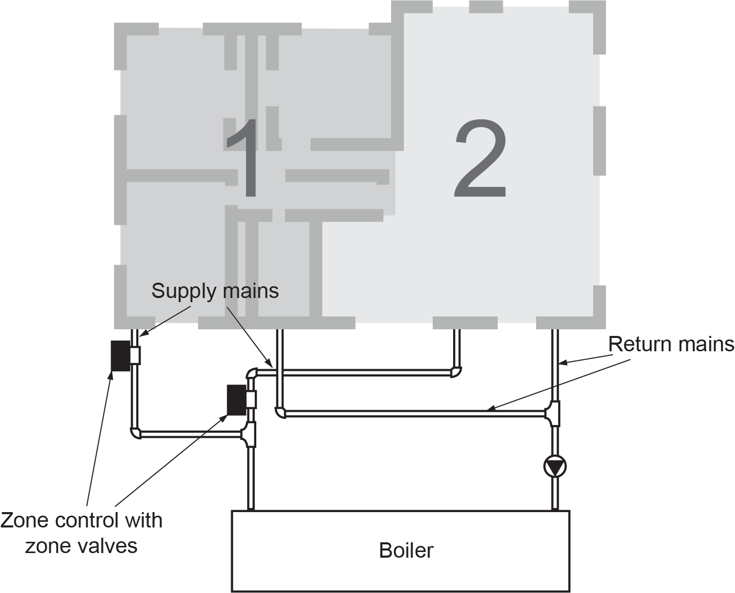
Each zone is controlled by a thermostat and zone valve. There is normally one zone for every major room or cluster of small rooms of a house (Figure 10).
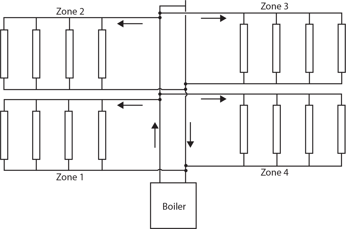
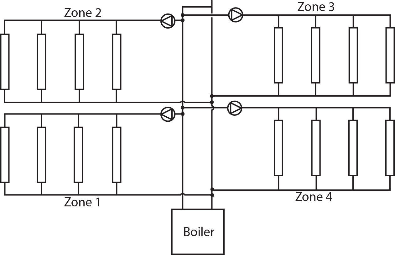
In a commercial system, each zone is typically a two-pipe system supplying many circuits that start and end near the boiler. There is normally one zone for every wing of a large building. The rooms within the wing are served by circuits that connect to the zone piping. Zone valves are installed on each circuit. Figure 11 shows a commercial system that has four zones, with four circuits in each.
Piping a System With Zone Valves
Every zone requires its own piping run, thermostat, and zone valve or pump. In a single-pump system, there is only one pump on the supply main or on the return main (Figure 12). The zone valves are shown installed on the return piping of each zone, near where the return main joins the boiler.
In a multiple-pump system (Figure 13), there is a pump on the supply piping to each zone and a zone or flow control valve on the return piping from each zone.
Balancing a Hot-Water Heating System
Balancing is the measurement and control process used to obtain the required flow in hot-water circuits. Balancing valves adjust the flow through circuits by restricting the flow. The system is balanced for flow before the operating controls are adjusted.
Here are some of the reasons why balancing is necessary:
- The circuits must be balanced to obtain design flow in the boiler.
- Fluctuations in flow reduce the efficiency of the heat transfer units and make control difficult.
- The distribution system must be balanced to make sure that all heat transfer units get design flow.
- The control loops must be balanced to bring about the proper working conditions for the control valves and to make primary and secondary flows compatible.
Balancing a Series Loop System
The series loop system has all of its heat transfer units connected end to end, so there is only one circuit and no balancing valves, but a number of series loops can be combined in a multi-zoned system. In that case, the zones are supplied by mains that are either direct-return or reverse-return, so the zones must be balanced accordingly.
The split-series loop system has two circuits that come off a common supply main. In a split-series loop system, a balancing valve is installed at the beginning of each circuit to be able to control the flow to that circuit.
Balancing a Diversion Tee System
The diversion tee system does not use balancing valves. Diversion tees are used to induce flow through the heat transfer units, so any throttling done on any of the runouts or mains would defeat the purpose of the diversion tees. Each heat transfer unit is equipped with a valve for allowing or stopping flow.
A number of diversion tee circuits can be combined in a multi-zoned system. The zones are supplied by mains that are either direct-return or reverse-return. The zones must be balanced according to the heating requirements for each zone.
Balancing a Reverse-Return System
The layout of a reverse-return system results in a well-balanced system. Balancing valves may be required in some complex systems, but the majority of the simple systems do not require balancing valves.
Balancing a Direct-Return System
Direct-return systems are normally installed for commercial or industrial applications and have many zones and sub-zones. Due to the complexity of balancing direct-return systems for large buildings, this work is often performed by contract firms that specialize in this process.
Every circuit of a direct-return system should have a balancing valve installed in the return pipe. If the balancing valve contains a drain, the location on the return pipe will also allow the circuit to be drained without having to drain other piping. Balancing valves are usually installed where they are easy to access and where there is minimal turbulence within the piping. Also, by placing all balancing valves in the same location relative to the other circuits, such as where they all connect to the system return main, it will be easier to balance the system flows.
To ensure accurate flow measurements at a balancing valve, install a straight pipe line a minimum of five pipe diameters upstream of the valve and two pipe diameters downstream. Do not install any fittings within these distances. If the balancing valve is installed downstream of a pump or other component that creates strong disturbances in flow, increase the minimum length of straight pipe upstream of the valve to 10 pipe diameters.
How Balancing Valves Affect One Another
Flow adjustment at one balancing valve disturbs the flow at the other balancing valves, including those that have already been adjusted. Balancing methods differ in how they compensate for this interaction.
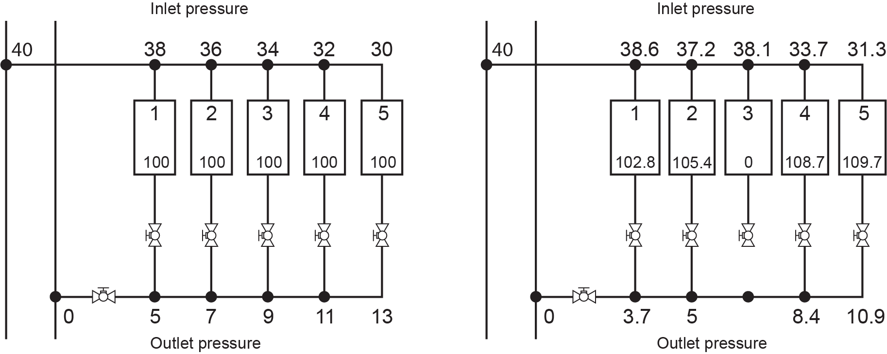
Figure 14 compares the flow through each of five heat units when all the balancing valves are open (left diagram) to when the valve on one unit is closed (unit 3 in right diagram). When that valve is closed, the flow in all the other heat transfer units will change, but not proportionally. The flow in the farther away heat transfer units will increase the most (from 100 to 109.7 in unit 5), while the flow in the closer heat transfer units will increase less, with the closest one increasing the least (from 100 to 102.8 in unit 1). The flow rate of 100 has been chosen at random to show the change and is not indicative of any system operation.
Optimum balancing is achieved when the heat transfer units all receive their design flow and the balancing valves impose the least restriction on the flow.
After balancing a system, it is important that the valve actuators (handles, etc.) are locked in place or marked to discourage any inadvertent tampering. If system maintenance is necessary, always take note of the balancing valve positions to ensure that they are reset properly after maintenance is completed.
 Self-Test B-4.4: Distribution System Installation
Complete the chapter Self-Test B-4.4 and check your answers.
If you are using a printed copy, please find Self-Test B-4.4 and Answer Key at the end of this section. If you prefer, you can scan the QR code with your digital device to go directly to the interactive Self-Test.

References
Skilled Trades BC. (2021). Book 1: Fuel gas systems, Heating and cooling Systems. Plumber apprenticeship program level 2 book 1 Harmonized. Crown Publications: King’s Printer for British Columbia.
Trades Training BC. (2021). B-4: Install hydronic heating piping and components. In: Plumber Apprenticeship Program: Level 2. Industry Training Authority, BC.
Media Attributions
All figures are used with permission from Skilled Trades BC (2021) unless otherwise noted.
A vertical pipe or duct that carries water, steam, air, or other fluids up through different floors of a building. It's used to move fluids between different levels or stories in a building. (Section B-1.2, Section B-4.1, and Section B-4.4)
