B-4.3 Distribution Systems
The piping mains connect the boiler to the heat transfer units. In some piping layouts, the piping mains connect directly to the heat transfer units, while in others, the piping mains connect to piping runs or branches that lead to the heat transfer units.
Types of Piping Configurations
There are a number of piping configurations available that deliver heated water from the source to the emitter, and the name of each configuration usually describes how the piping arrangement is installed.
The piping layouts in hot-water heating are named as follows:
- One-pipe series loop
- One-pipe split-series loop
- One-pipe diversion tee
- Two-pipe direct-return
- Two-pipe reverse-return
- Two-pipe primary/secondary
Radiant panels are essentially heat emitters and, therefore, are not categorized as piping layouts. The specifics of radiant heat systems will be covered in Level 3 of Plumber and Steamfitter/ Pipefitter Apprenticeship training.
One-Pipe Systems
In one-pipe systems, hot water is circulated through a single pipe to a number of heat transfer units and back to the boiler. In some cases, the return pipe from one heat transfer unit is the supply pipe for the next unit. In all one-pipe systems, the heat transfer unit nearest to the heat source will receive much hotter water than units farther down the line. One-pipe systems are most common in residential buildings because of their lower installation cost.
As in all hydronic systems, air vents are required at every high point so that air does not form a blockage and prevent water from circulating. As well, drains are required at all low points to allow servicing of piping and equipment.
Series Loop Systems
In a series loop system (Figure 1), the supply main joins directly to the first heat transfer unit, the return pipe from this unit supplies the next unit, and so on. Finally, the return pipe from the last heat transfer unit returns the water to the boiler. It can be said that the heat transfer units are part of the piping main. Series loop systems and one-pipe systems are very similar.
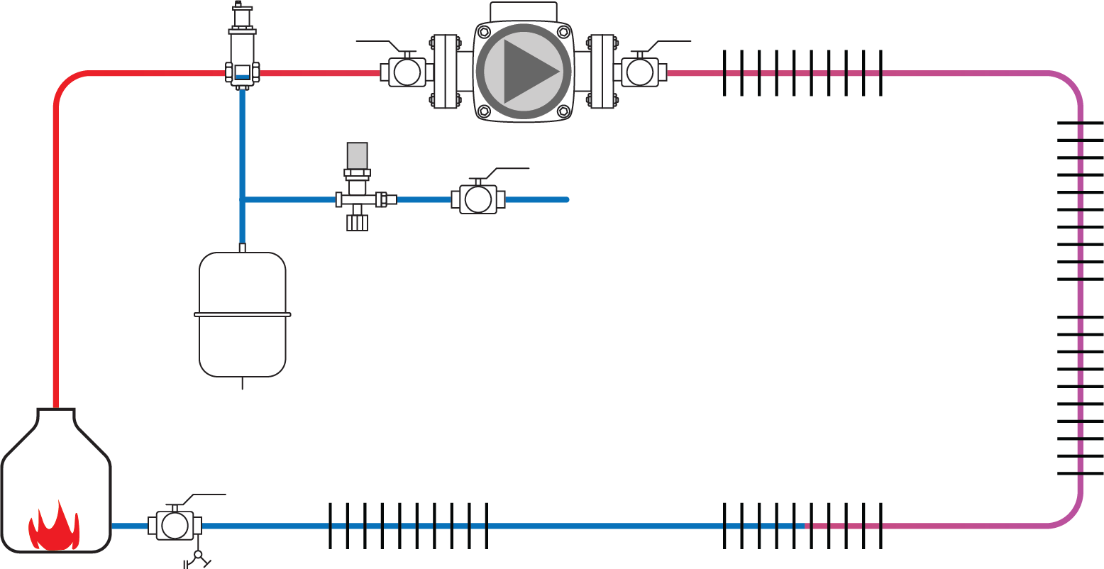
The series loop system is simple and is the least expensive system to install, but its heat transfer units cannot be individually shut off and should be progressively longer/larger in size, to give them equal heat output, the farther they are from the boiler. This is due to the lower water temperature available in the farther reaches of the system. A single pump responding to a lone thermostat controls the heat in the entire zone. This system is normally used in apartments or small single-family dwellings where the temperature will not vary much between rooms and the heat emitters are finned-tube baseboards. The temperature in any room is adjusted by allowing more or less airflow through each finned-tube baseboard cabinet by opening or closing the damper on the cabinet (see
B-3 Hydronic Transfer Units).
To avoid flow problems, one pipe size (normally [latex]\tfrac{3}{4}[/latex] in. NPS) should be maintained throughout a loop. The length of each loop and number of heat emitters on it becomes very important because the water releases heat and becomes cooler as it travels through each heat transfer unit. If return water to the boiler has had too much heat removed from it, condensation problems could occur, causing premature heat exchanger failure due to corrosion inside the combustion chamber. Therefore, a rule of thumb in the industry is that no more than 60,000 to 70,000 BTU/h (18–20 kW) should be allocated to each circuit in the system.
Split-Series Loop Systems
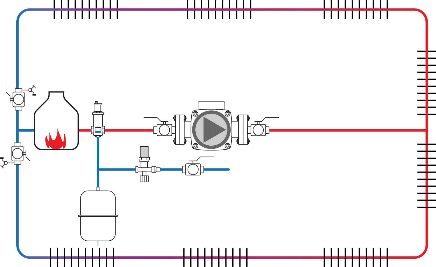
The split-series loop system (Figure 2) is a version of the series loop system, with the main difference being that the piping is split into a number of loops. Each loop is controlled by a thermostat connected to a zone valve that controls the heat flow to the heat transfer units within that loop.
In the split-series loop system shown in Figure 2, the supply main is piped from the boiler to the farthest outside wall. The main then splits and water is directed to each of the two loops. The return mains individually return the water to a point near the boiler, where they join together to become the boiler return. There can be more than just two loops in a split-series loop system, and the heat source would be sized to supply all the loops, but each loop is still limited to no more than 60,000 to 70,000 BTU/h output.
The split-series loop system is suitable for larger buildings where there is a larger heat load, such as in small apartment blocks or similar structures.
One-Pipe Diversion Tee System
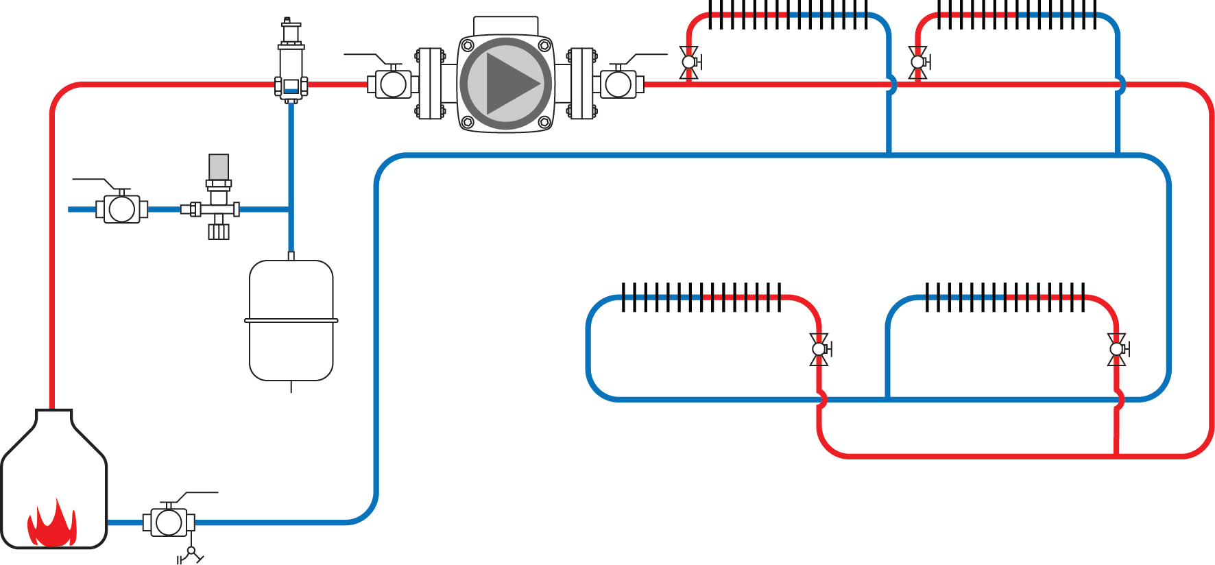
A diversion tee or Monoflo system is a one-pipe system, but the heat transfer units are placed on branch circuits, parallel to the main supply pipe. Any of the units may be shut off individually without disturbing the flow of hot water in the rest of the system. The layout of a one-pipe diversion tee system is shown in Figure 3.
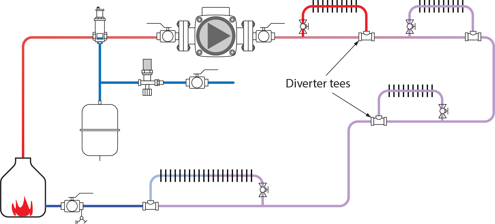
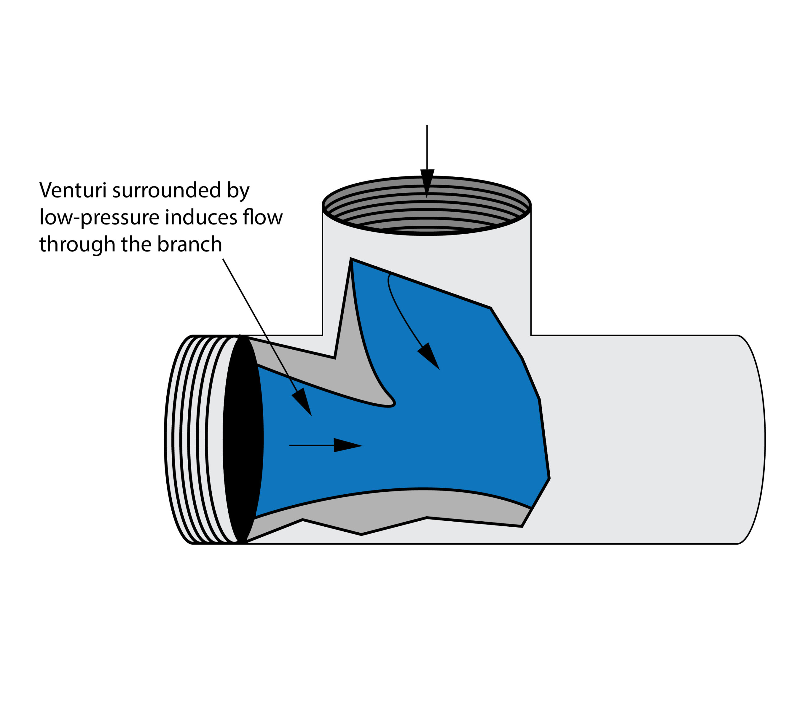
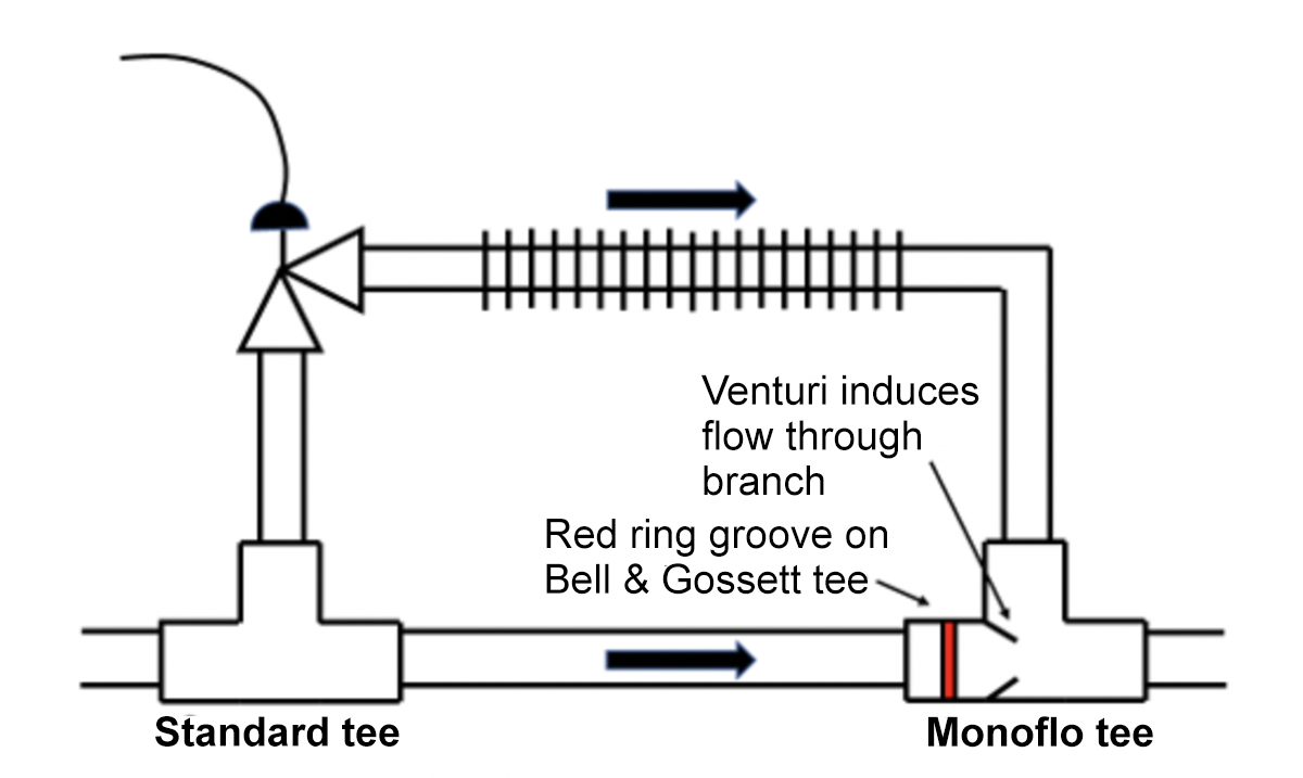
Diversion tees (Figure 4) are installed on the piping main to create flow through the branch piping. Monoflo is the trademarked name for a diversion tee that has been specifically engineered for use in hot-water heating systems. It operates through the use of a venturi and applies Bernoulli’s principle, which states that “where velocity is greatest, pressure is least.” For water to flow through the narrow opening within the tee, it must increase in velocity. This drops the pressure in an area behind the nozzle, which is where the branch outlet is connected, and water is drawn through the branch.
To correctly install a Bell & Gossett (originator of the fitting) diversion tee on an upfed system, place the Monoflo tee on the heat emitter’s return connection, with the red ring groove closest to the standard tee on the supply connection. Only one tee is normally needed due to the tendency of hot water to rise easily through the standard tee on the supply (Figure 5). If the heat transfer unit has a lot of flow resistance through it, then install two Monoflo tees, similar to the downfed configuration described below. For upfed heat transfer units, the tees should be installed at least the length of the heat transfer unit apart.
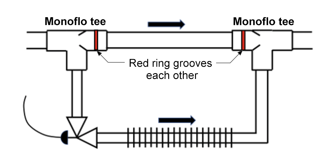
Downfed heat transfer units are located below the supply mains and require more definite flow diversion to make heated water fall below the main (Figure 6). Monoflo tees are installed on both the supply and return connections, with the red groove rings on the tees facing each other. The Monoflo tee on the supply acts to divert water flow through the branch outlet.
The diversion tee system is adaptable to almost any type or size of building, from a small single-family residence to a multi-storey office to an apartment complex. For more specific installation requirements, always consult the manufacturer’s literature.
Two-Pipe Systems
Two-pipe systems have distinct supply and return mains. Water from the supply main is fed to each heat transfer unit and ends at the last HTU. The return water from each HTU is collected in a return main and delivered back to the boiler.
The supply main is gradually reduced in size as it feeds the circuits and, similarly, the return main is gradually increased in size as it receives the return water from each circuit. In this way, each heat transfer unit can and should receive water at the same temperature as when it left the boiler.
Two-pipe systems are generally found in large commercial or industrial buildings, or in smaller systems where better control of heat and flow is desired. Two-pipe systems are categorized as either direct-return or reverse-return.
Two-Pipe Direct-Return System
In a two-pipe direct-return system (Figure 7), each heat transfer unit has a supply line of hot water from the boiler and a return line to the boiler. This is also known as a “first fed, first return” system.
A difficulty with direct-return systems is that the circuits from the boiler to different heat transfer units and back to the boiler are usually of different lengths. This difference in length influences the flow of water to certain units, which cause an imbalance of heat transfer. To counteract this imbalance, larger diameter pipes can be used for the longer circuits or the size of the heat transfer units on those units can be increased. The most common method of balancing the heat transfer is to install balancing valves at each heat transfer unit to restrict the flow. The heat transfer unit nearest the boiler would have its flow restricted more than those farther out along the supply line, with the farthest heat transfer unit not likely needing any flow restriction at all. When balanced, the resistance to flow through all the heat transfer units should be roughly equal to that of the furthest circuit.
A direct-return system can supply different amounts of heat simultaneously to a variety of equipment. The equipment may include heat exchangers and heat transfer units.
The direct-return system is unpopular for residential systems because it is:
- Difficult to balance
- More expensive to install because of the balancing components
- More expensive to maintain because of the balancing components
Two-Pipe Reverse-Return System
The two-pipe reverse-return system (Figure 8) was developed to provide a better balance of heat transfer between circuits of different lengths without the need for balancing valves. In the reverse-return piping layout, each circuit is of nearly equal length. The heat transfer unit that has the shortest supply pipe route has the longest return pipe route. Pipe size must still be matched to flow requirements in each section.
This system is also known as the “first fed, last return” system and is the most common system installed in commercial buildings.
Home-Run Distribution System
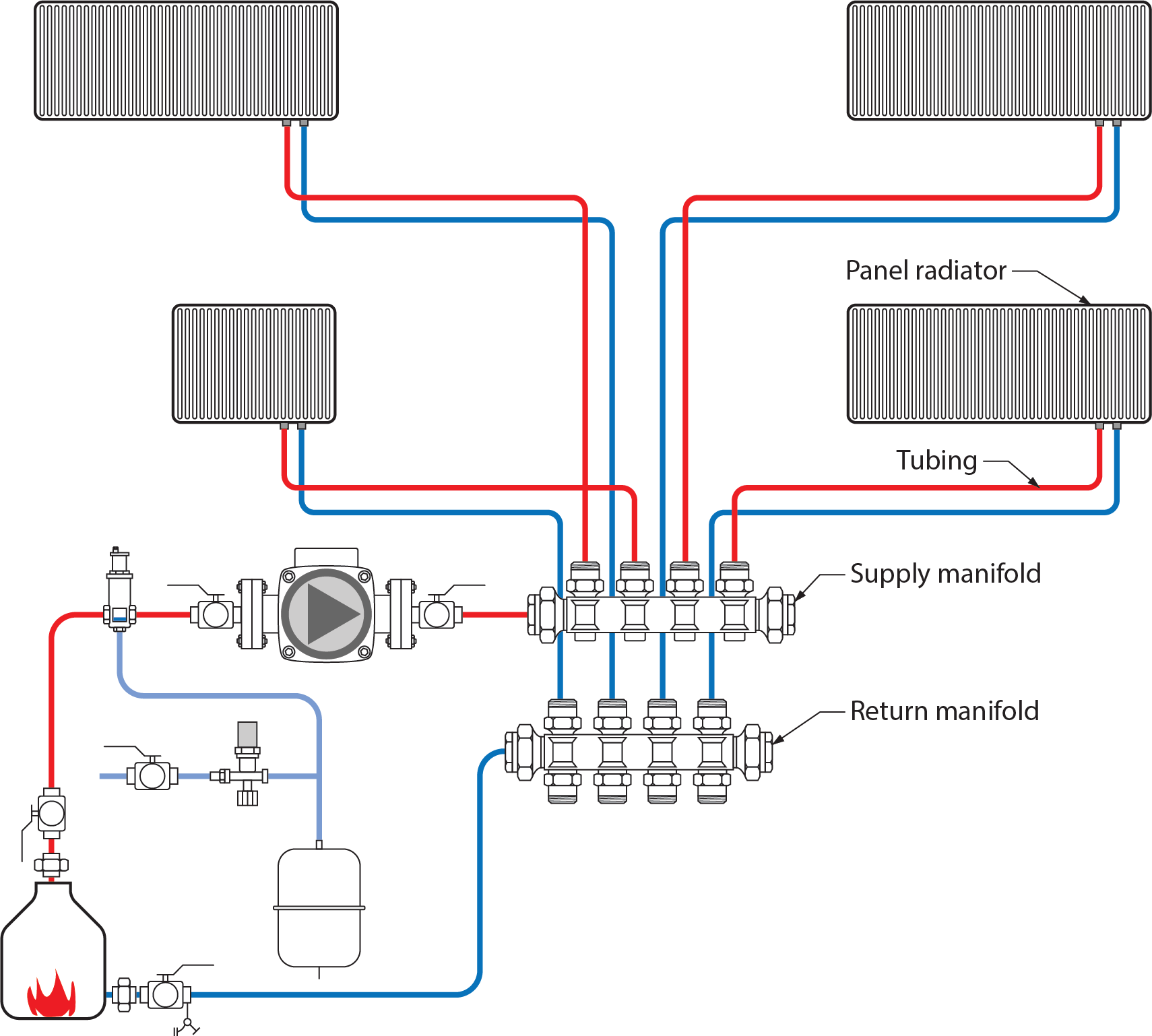
In the previously mentioned systems, it is assumed that rigid piping is used. The introduction of PEX (cross-linked polyethylene) in the piping industry has led to a piping system known as the home-run distribution system (Figure 9).
A home-run system consists of a supply and return manifold station placed in an easily accessible location within each dwelling, such as one for each storey. Supply and return mains to the manifolds are piped in a reverse-return configuration. In this way, the manifolds are treated much like heat transfer units and should have relatively equal temperatures of supply water available. From the supply manifold, a separate small-diameter PEX tube, such as [latex]\tfrac{3}{8}[/latex] in. or [latex]\tfrac{1}{2}[/latex] in., is run to each heat emitter and then returns back to the return manifold. In this way, with throttling valves on the tubing at the return manifold connections, the flow of water to each heat emitter can be controlled. It is similar to a radiant floor system in that each run leaves the supply manifold and returns to the return manifold, but a home-run system will have different heat emitters, such as a finned-tube baseboard (wallfin).
The small diameter and flexibility of the PEX tubing allows for quick and easy installation. Some of the other benefits of the home-run system include the following:
- The heat output of each room can be individually controlled by flow rates.
- Water is delivered to each heat emitter at approximately the same temperature.
- Manifolds can be used in conjunction with a variety of heat emitters.
- Balancing valves can still be used to regulate flow through each separate home run.
Hydraulic Separation
In a hydronic system, it is often necessary to have two or more circulators operating simultaneously within the same system. Circulators work on the principle of creating a pressure differential between the inlet and outlet to move water. Ideally, each circulator works independently of the other, and the pressure differential created by one does not affect the other. When this occurs within a system, it is referred to as hydraulic separation. If the circulators create a situation where they interfere with each other, undesirable flow conditions can occur.
Primary/Secondary Systems
The degree to which two operating circulators interact with each other depends on the head loss of the piping path they have in common. Head loss is “pump-speak” for pressure loss. All systems need a pressure differential to create flow. If this common piping has low flow resistance through it, then very little head or pressure loss occurs.
The system shown in Figure 10 contains multiple pumps, each of which circulates water through a circuit. Hydraulic separation is achieved when the working of one pump does not affect the working of another. Once again, hydraulic separation is created when the head or pressure loss through common piping is limited. In Figure 10, the designer used what is known as closely spaced tees to achieve this effect. Spacing the tees closely together on common piping minimizes head loss between tees, thus ensuring hydraulic separation. If the tees were even only a few feet apart, there would be enough friction loss between the tees for flow through the primary circuit to cause small flows in the secondary circuit, which must be avoided.
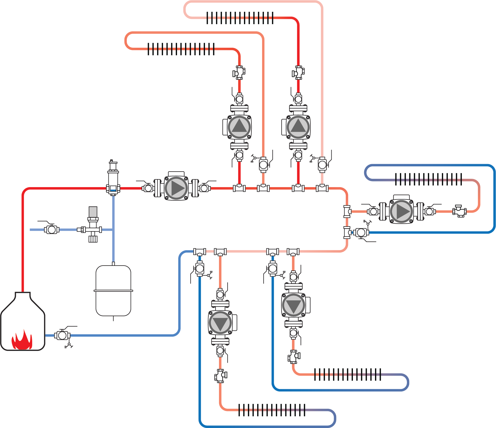
The system illustrated in Figure 10 uses a piping system referred to as a primary/secondary system. Primary/secondary piping, originating in the 1950s, is one way to achieve hydraulic separation. Back then it was mainly used in large commercial heating and chilled water-cooling systems. Advances in technology and the complexity of residential and small commercial systems have led to an increase in the use of primary/secondary systems in those areas.
These systems consist of a primary circuit with secondary circuits connected to it. The primary circuit consists of a pump and piping large enough to carry the expected heating water for the entire system and long enough to have space for the closely spaced tees for the secondary circuits. This circuit has no other function than to keep a hot supply of water flowing through it.
The secondary circuits involve the heat source(s) and different types of heating loads. These loads could be for space heating, domestic water heating, pool heating, or any other heating load desired. Primary/secondary piping is ideal for systems with multiple smaller boilers, rather than one large boiler, feeding into the primary circuit as needed or when different heating circuits are connected to the same boiler.
All primary/secondary systems require protection against the tendency for hot water to migrate into and through inactive secondary circuits. This occurs because the less-dense hot water tends to rise. Although the closely spaced tees offer hydraulic separation when the pump is operating, they do not protect against thermal migration (thermosiphoning).
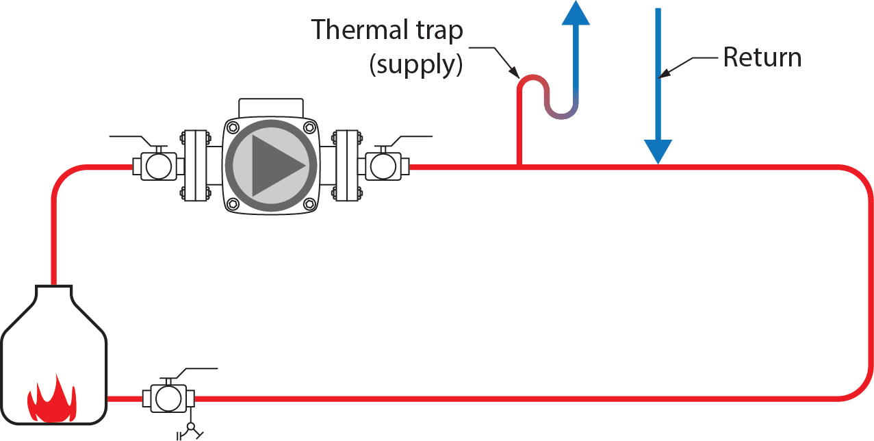
Thermal migration can be limited using circulators with integral spring-loaded check valves or installing an external spring-loaded check valve, known as a flow check. Thermal migration can also be limited with the use of a thermal trap (Figure 11). The thermal trap discourages convection currents from moving through it and into the system.
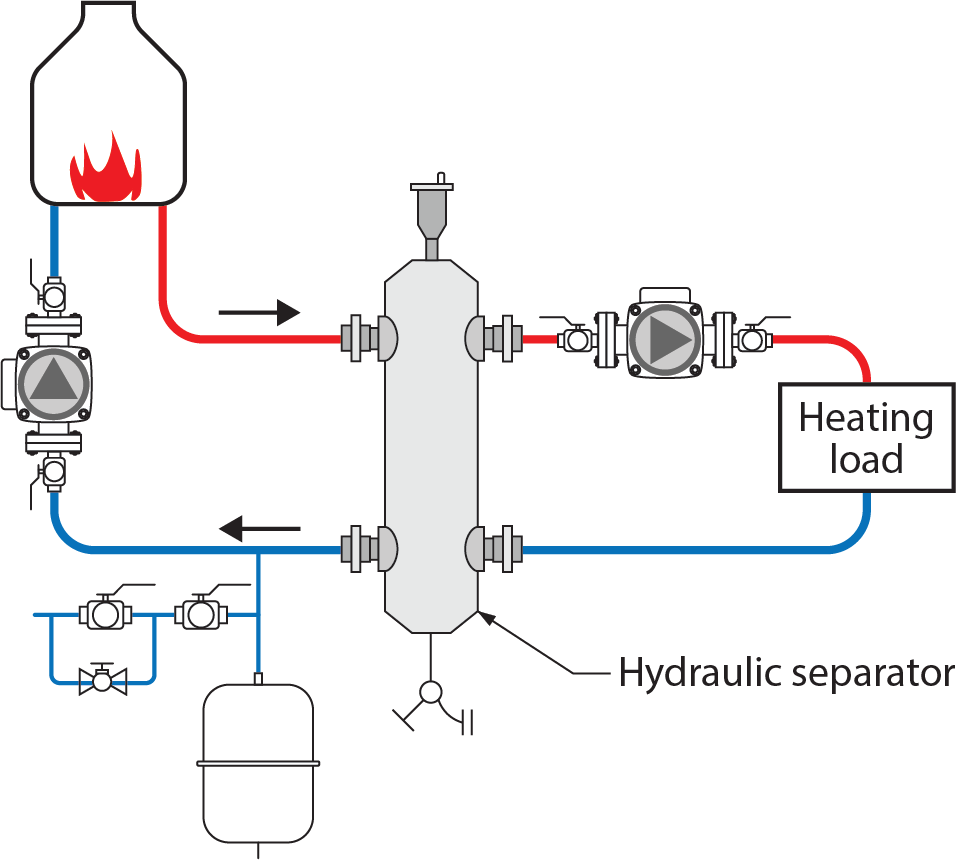
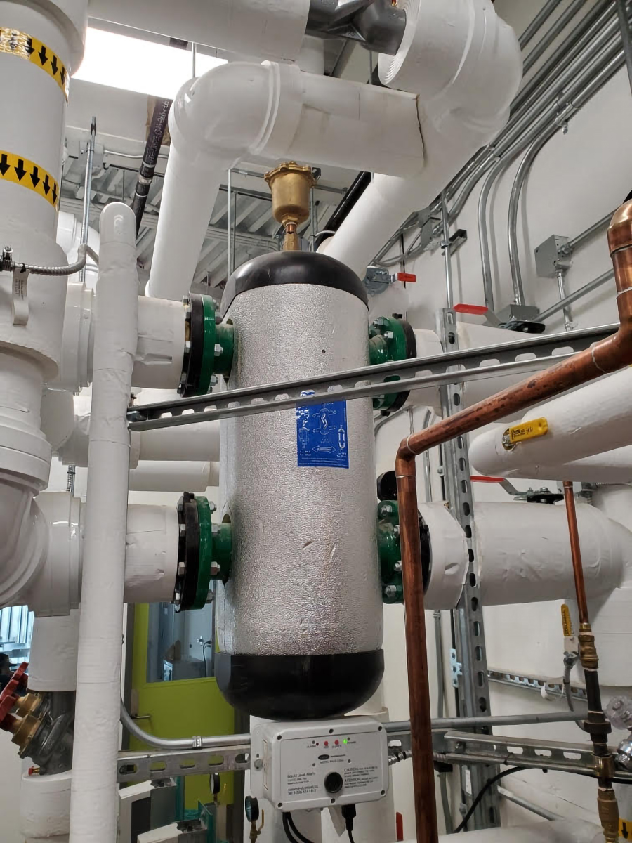
Besides using closely spaced tees, hydraulic separation can also be accomplished using a hydraulic separator or low-loss header. Both use a large-diameter vertical chamber to slow down the water flow rate. This vertical chamber is generally three times larger in diameter than the diameter of the system piping. Slowing the water down creates very little head loss through the chamber and ultimately creates the hydraulic separation needed between systems to be effective (Figure 12).
The unit shown in Figure 13 also provides high-efficiency air and dirt separation for the system.
 Self-Test B-4.3: Distribution Systems
Complete the chapter Self-Test B-4.3 and check your answers.
If you are using a printed copy, please find Self-Test B-4.3 and Answer Key at the end of this section. If you prefer, you can scan the QR code with your digital device to go directly to the interactive Self-Test.

References
Skilled Trades BC. (2021). Book 1: Fuel gas systems, Heating and cooling Systems. Plumber apprenticeship program level 2 book 1 Harmonized. Crown Publications: King’s Printer for British Columbia.
Trades Training BC. (2021). B-4: Install hydronic heating piping and components. In: Plumber Apprenticeship Program: Level 2. Industry Training Authority, BC.
Media Attributions
All figures are used with permission from Skilled Trades BC (2021) unless otherwise noted.
- Figure 13 Hydraulic separator is by TRU Open Press and can be used under a CC BY NC SA license.
A way of moving water in a building where the water comes in from the bottom and gets pumped up to higher floors. This is often used in places where the water pressure isn’t strong enough to reach the top on its own. (Section B-4.3)
A process where a liquid moves naturally without the need for a pump, because of temperature differences. When a liquid gets heated, it becomes less dense and rises. Cooler, denser liquid then moves in to take its place. This creates a natural circulation of the liquid. It's often used in heating systems and solar water heaters. (Section B-4.3)
