B-3.1 Hydronic Heat Transfer Units
Heat in a hydronic heating system is generated at the heat source. Consider a boiler as an example. A boiler heats water to temperatures as high as 88°C (190°F), then the distribution piping system carries this heated water throughout the building. At some point along the way, a portion of that heat is released into the space that requires it. This is the point where heat transfer units, aka heat emitters, are installed. They take the heat out of the water and transfer it into the room.
Hydronic heating has the advantage of offering many options to choose from when selecting heat transfer units. Small baseboard wallfin units operating at high temperatures can do the same job as low-temperature radiant panels that use a large surface area. Designers take into account variables such as comfort, aesthetics, and control when designing systems and choose transfer units accordingly. Because of the wide variety of heat transfer units available, designers are also able to choose transfer units that meet the architectural requirements of a building. The ductwork involved with forced-air heating systems may require dropped ceilings in the room below, whereas a radiant panel in-floor heating system requires no additional space to be used.
Although there are many classifications of heat emitters, this section will group them into four categories:
- Gravity circulating convectors
- Forced circulating convectors
- Radiators
- Radiant panels (in-floor heating)
Gravity Circulating Convectors
Convectors are so named because they operate on the principle that when air is heated, its density decreases, and colder, denser air will force the heated air upward. Gravity or “passive” convectors (Figure 1) use natural air currents to move heated air through them. The coldest air in a room is near the floor, so the cabinet of a gravity circulation convector is open at the bottom to allow cold air to enter. Hot water flowing through the tube heats the fins by conduction.
The large surface area of the fins transfers the heat to the air in contact with them, also via conduction. The now-warmed air rises due to its buoyancy and mixes with the rest of the room air. The design of the gravity circulation convector is such that the cabinet does not become hot, so it will transfer very little heat through radiant means.
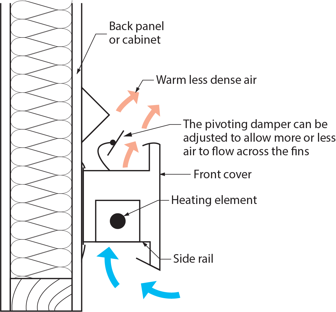
Gravity circulation convectors are either surface-mounted or recessed into the wall. Insulation behind the back of the cabinet prevents heat loss through the wall. Brackets attached to the back of the cabinet support the finned tube. The front panel of the cabinet can be removed for access to the tube and air vent, and the pivoting damper can be adjusted to allow more or less air to flow across the fins
Residential circulating convectors are mounted at baseboard level, beneath windows. Commercial-grade convectors are normally found in stairwells and common areas.
Finned Tube Baseboard Convectors
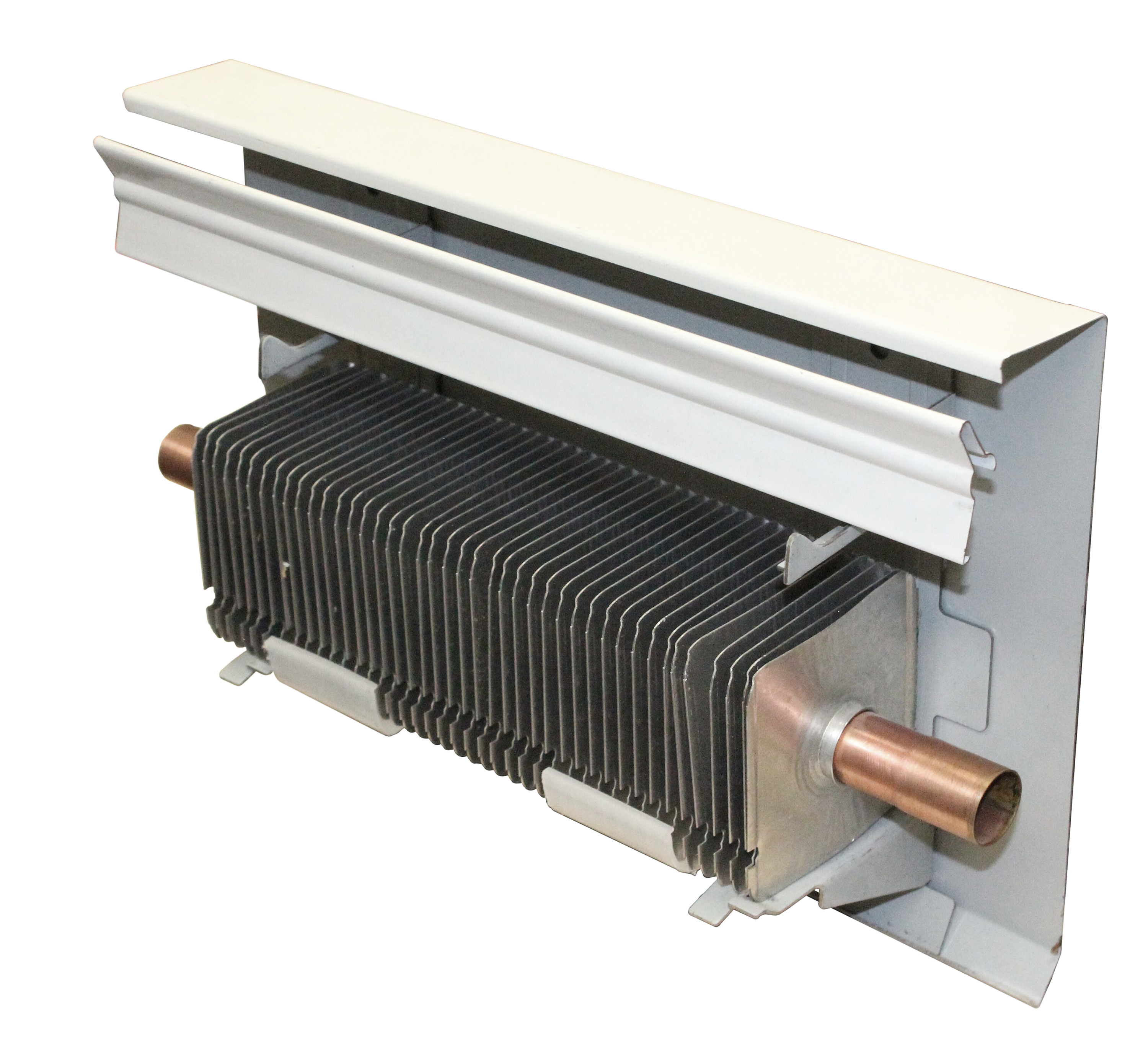
The finned tube baseboard convector (also known as “baseboard wallfin”) has historically been the most common hydronic heat emitter used in residential and small commercial applications. Figure 2 shows two views of a typical finned tube convector (with a back panel or cabinet).
The heating element is a single copper tube with aluminum fins. When heated water is moved through the copper tube, heat is transferred by conduction to the aluminum fins. The cold air that has been trapped between the fins begins to warm through contact with the fins, and eventually this warm, less dense air rises. Colder, denser air displaces the warm air and thus begins the convection currents that warm the room. Because the heat is quickly moved away from the convector, there is not enough time for the convector to warm up and create radiant heat, so almost all of the heat created for the room is through air convection. As well, the white cabinet tends to reflect the heat back into itself rather than absorb the heat, so it emits very little radiant heat.
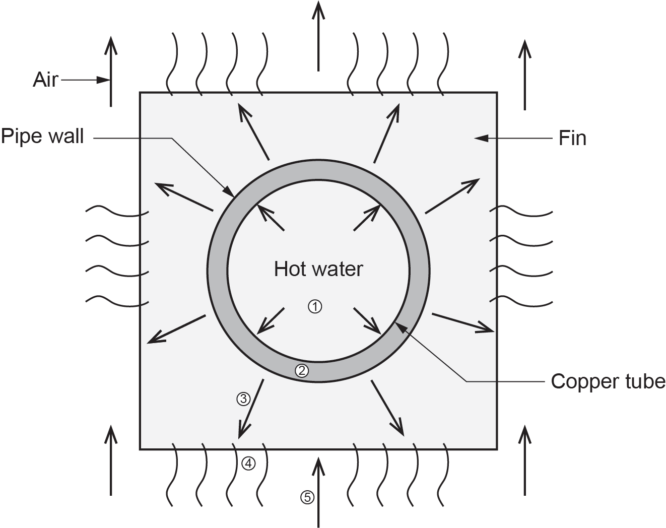
The finned tube baseboard convector is encased in a housing, also known as a cabinet, designed to allow for airflow in and out of the unit. Movable brackets attached to the back panel of the cabinet support the heating element or finned tube, the front panel, and the adjustable louvre. The adjustable louvre regulates airflow. Closing the louvre slows or stops the flow of air and eventually stops or slows down the flow of heat. Figure 3 shows how the heat is transferred from the water into the convector and then into the room.
Baseboard convectors for residential use are typically 230 mm (9 in.) high and extend less than 100 mm (4 in.) from the wall. However, they do come in various sizes. Convectors should be mounted below windows to balance the cold drafts from the windows. When the air in contact with the window is cooled by heat loss through the glass, it moves downward. If a convector is mounted below the window, the cool downdraft will mix with the warm air that is rising from the convector. Together these drafts produce a more even room temperature. To allow the convector to function as designed, nothing should obstruct the movement of air through the unit and the room. Homeowners must keep this in mind when placing furniture and drapery near the baseboard wallfin.
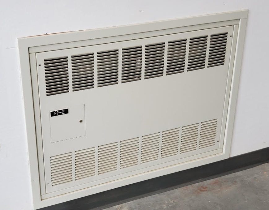
Commercial-Grade Wall-Mounted Convectors
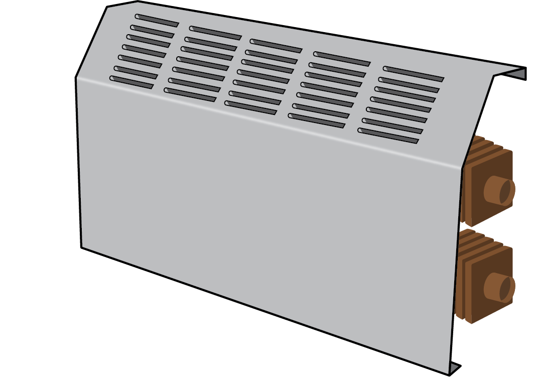
Commercial wall-mounted convectors are the modern counterpart of the cast-iron radiator. A wall-mounted convector is not nearly as heavy as a cast-iron radiator and typically extends only about 125 mm (5 in.) from the wall, however, the sizes may vary. Wall-mounted convectors are used in commercial applications and large buildings, such as schools. They are normally installed below windows, in stairwells, and in stairway landings.
The heating element of the wall-mounted convector has a manifold and several tubes running through the fins.
Figure 4 shows a multi-tube wall-mounted convector. A wall-mounted convector works in the same manner as a finned tube baseboard. Cool air enters the bottom opening and gets trapped between the aluminum fins. As this air is warmed, it rises and exits through the top of the unit. Cool air replaces this warm air, establishing convection currents.
Forced Flow Systems or Fan Coils
Gravity convectors rely on the differences in temperature and density of the air to create convection air currents that move the heat. Forced flow systems combine a heating element, which is a finned tube heat exchanger, similar to those in the gravity convectors, and a fan or blower to move the air. The concept is similar to that of a forced-air furnace — in both cases, warm air is circulated using a fan, but the heat sources differ. A furnace uses hot flue gases on the inside of its heat exchanger, whereas, in a forced flow convector, the hot water inside the tubing is the heating medium.
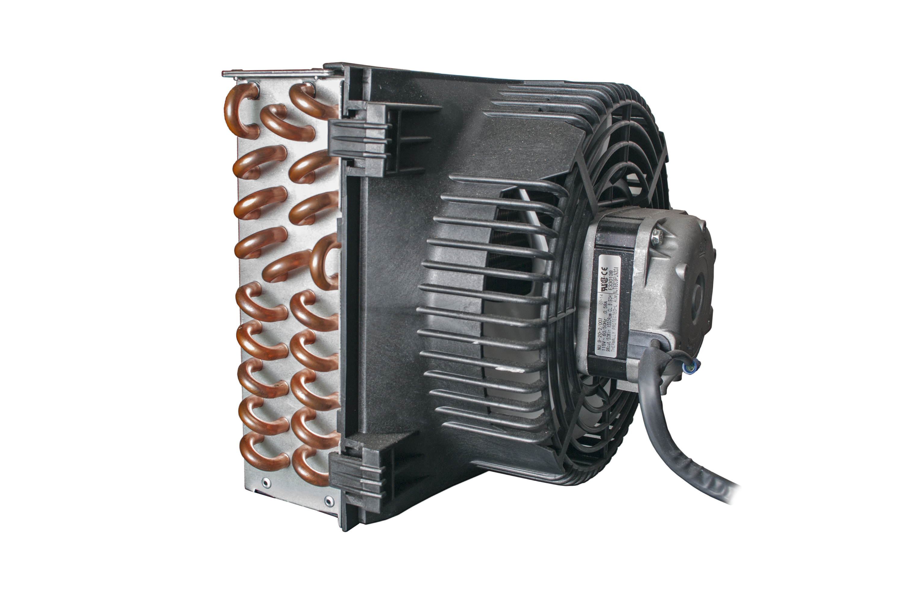
A hydronic fan coil (Figure 5) is a type of forced flow convector that can best be compared to a radiator in a car. It consists of small-diameter tubing with a large surface area of aluminum fins attached to it and uses a fan to push air through it. The principle of heat transfer is similar to that of the baseboard wallfin, except the fan coil has more tubing of smaller diameter that the water has to push through. Rather than relying on air currents, the air is forced over the finned tubes using a fan. This increases the heat transfer rate but also increases the resistance to flow that the circulator has to overcome.
Consequently, stronger pumps may be required on fan coils than on baseboard wallfin or convectors. When heating is required, a fan on the upstream side of the coil pushes air across the coil. The air picks up heat and is pushed out directly into the room or into ductwork. Other names used to describe particular types of fan coils are unit heaters, duct heaters, and kickspace heaters. The different names generally relate to their location, but essentially, they all work on the same principle.
Because forced flow systems use a fan to transfer heat from the coil surface to a room, these systems are much more responsive than gravity convection systems. They generally have little thermal mass and low water content, which allows them to respond to a call for heat quickly.
Forced-air heating can cause more dust movement and more noise from the fan than a gravity system. An installer must also consider the fact that as forced flow systems are equipped with a fan, a source of line voltage, wiring, and other electrical controls associated with the fan are required.
Unit Heaters and Overhead Fan Coils
Unit heaters and overhead fan coils are mainly used in commercial buildings, where it may be advantageous to deliver heat from above. This allows the hydronic piping to be kept close to the ceiling and avoids having to run piping down to the floor level in areas where that might be difficult. An example of this would be a large open space, such as a warehouse. Machine shops, service garages, and supermarkets are all areas that would benefit from the installation of unit heaters.
Unit heaters have closely spaced fins on their tubing, much the same as fan coils. The fan forces air between the fins, allowing unit heaters to transfer great quantities of heat, making them suitable for large commercial and industrial applications.
Unit heaters are installed high above the floor. The warmed air is directed downward by a series of louvres attached to the discharge side of the unit. Because they are mounted high in a room, they do not produce uncomfortable drafts at head level. The heat from one unit heater can be circulated through a large area by the action of a few well-placed ceiling fans.
Unit heaters can be either vertical or horizontal. Horizontal units are less expensive, but vertical units will heat a larger area. Smaller units are less expensive than larger ones, although smaller units require higher water flow rates, larger pipes, and a stronger pump to achieve the same level of heat transfer.
Vertical Unit Heaters
Vertical unit heaters, also called projection unit heaters, push air downwards and are mounted near the ceiling. The vertical unit heater has a circular heating element. This element has a manifold tube running through the vertical fins that allows air to flow through the unit (Figure 6). The fan draws the air in through the heating element then forces the heated air toward the floor. Deflecting louvres below the fan can be adjusted to direct the air, or a diffuser cone can be used to decrease drafts.
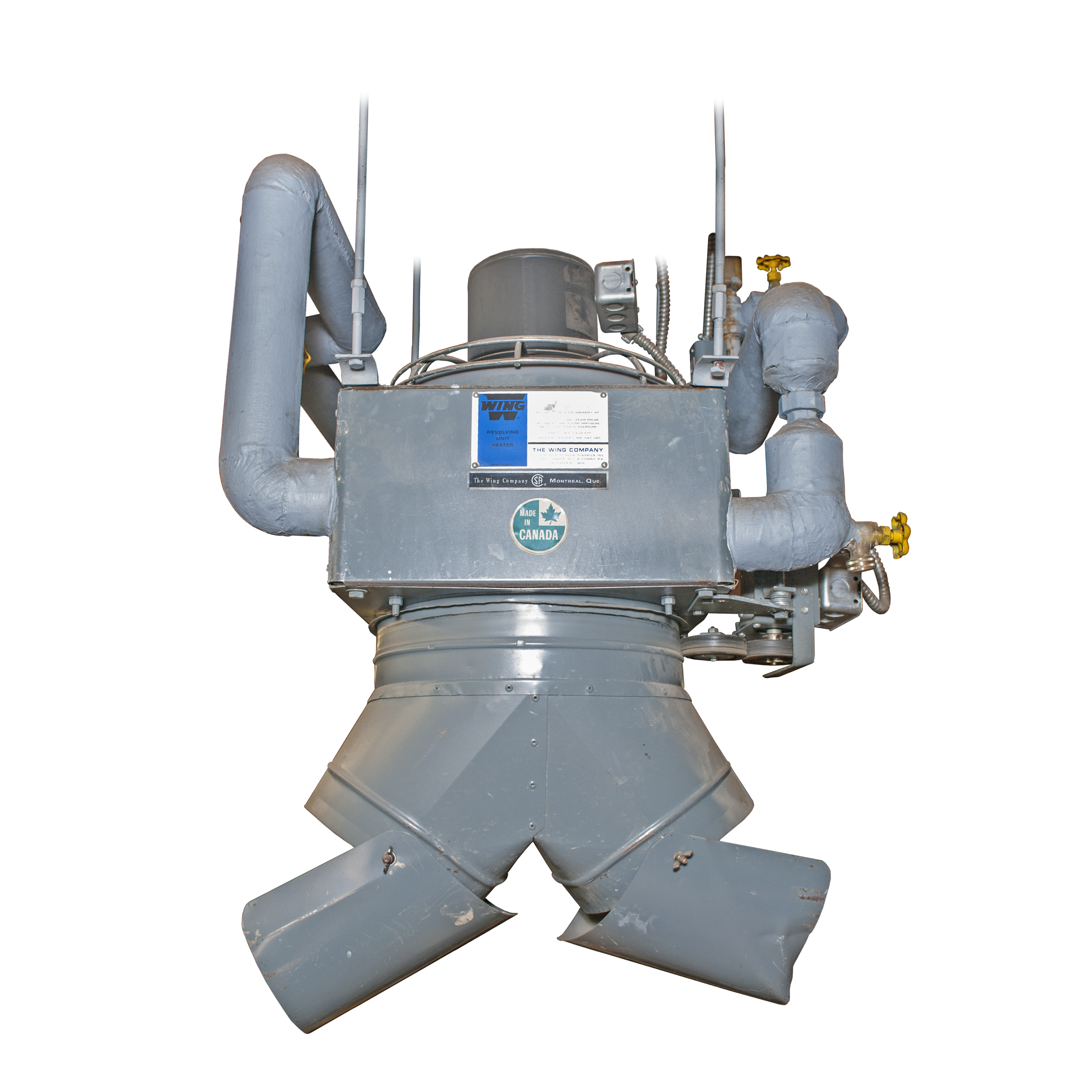
Vertical unit heaters create downdrafts and updrafts; however, they can often produce warmer and cooler spots within a room. Warm downdrafts occur directly under the unit, and updrafts occur in other areas. Well-positioned vertical unit heaters can mix the air to give even temperatures throughout, and will not create excessive drafts near the floor.
Horizontal Unit Heaters
Horizontal unit heaters (Figure 7) move air at a lower velocity than vertical unit heaters. In situations where unit heaters must be installed at lower levels, horizontal units provide more comfort due to their ability to direct airflow via adjustable discharge deflectors. Horizontal unit heaters should be used in areas less than 4.5 m (15 ft) high, where there is no permanent obstruction to airflow.
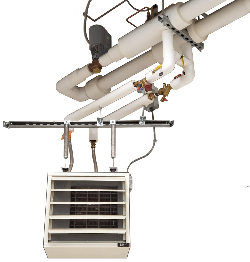
Because of their lower velocity, horizontal unit heaters are used in groups to circulate air throughout a large area. Normally, a fan is mounted behind the heating element, and adjustable air deflectors are mounted in front of the heating element.
Kickspace Heaters or Under-Cabinet Fan Coils
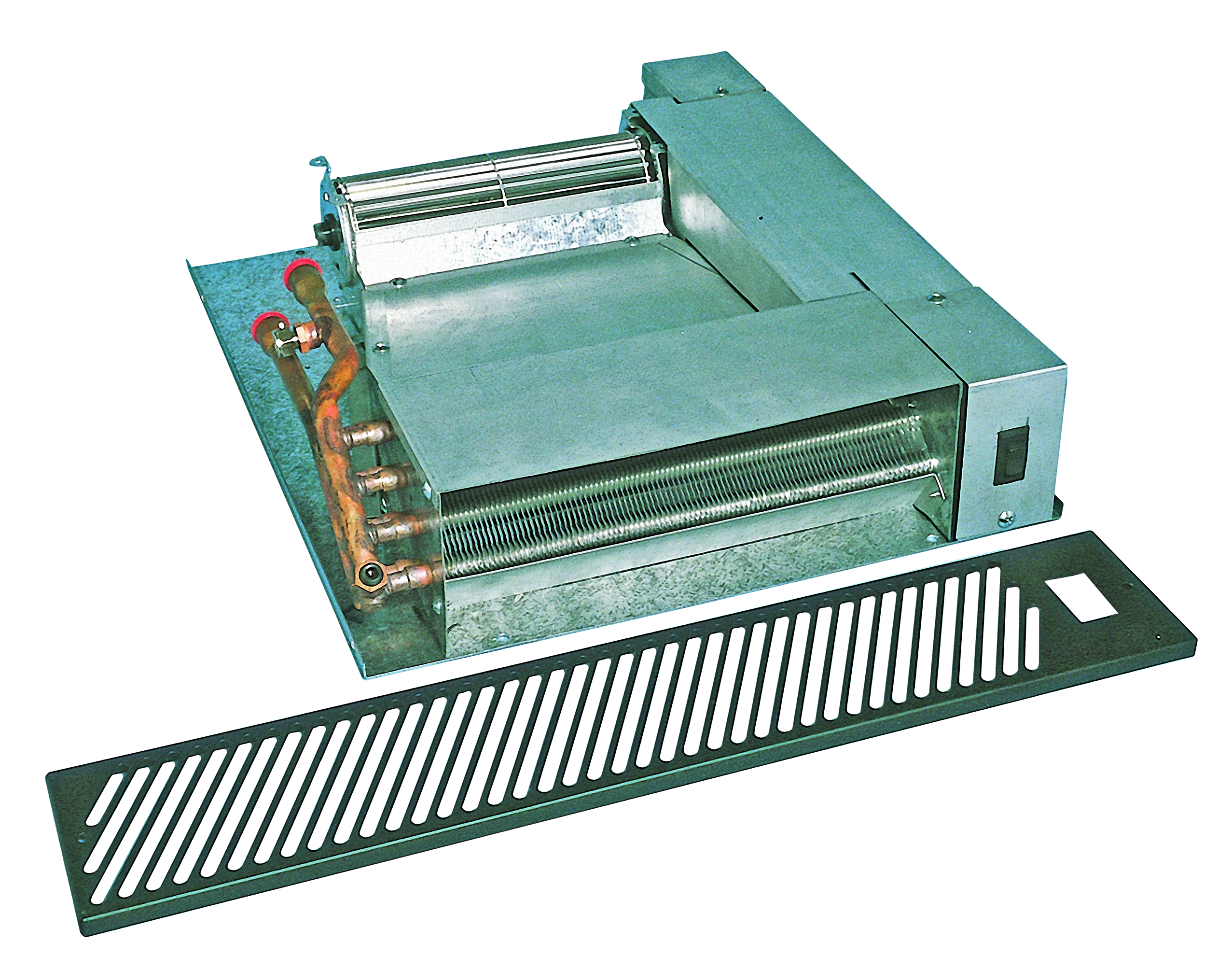
Kickspace heaters (Figure 8) are also referred to as under-cabinet fan coils. These transfer units are designed to be installed in kitchens or bathrooms in the “kickspace” below cabinets. They heat a room in which wall space is limited, and serve as supplementary heat for a radiant floor system. They operate similarly to a unit heater in that hot water is circulated through a finned tube coil. A fan draws air into the kickspace heater and across the coil and moves the heated air out into the room.
Forced-Flow Wall-Mounted Convectors
Forced-flow wall-mounted convector units can also be called wall-mounted fan coils. They are identical to a wall-mounted gravity convector except for the addition of a fan that draws air in through the bottom and moves heated air out through the top. Another version of the convector is recessed into the wall (Figure 9).
Using Fan Coils for Cooling
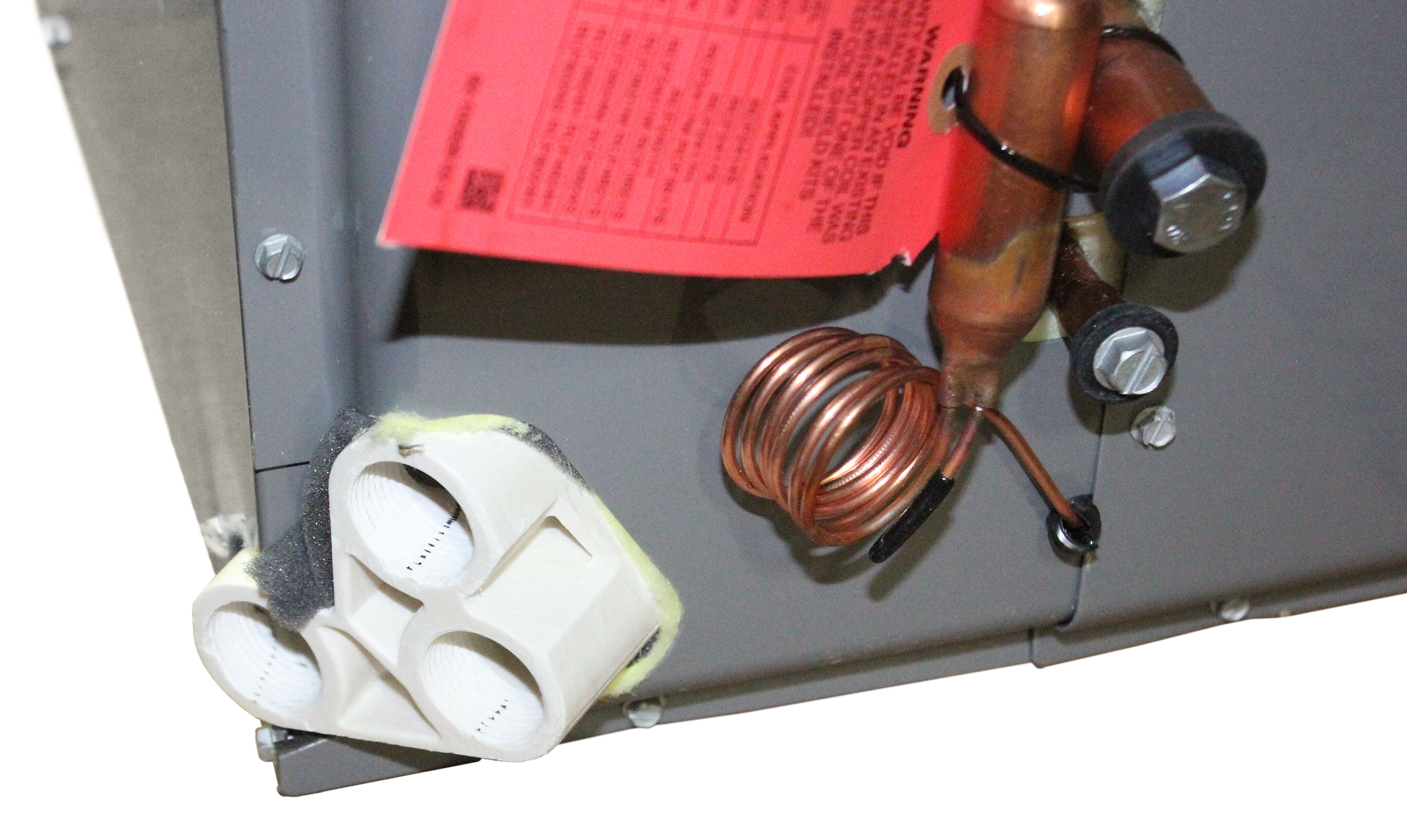
Some hydronic systems can supply heating and chilled water to fan coils in ductwork, but these installations are normally limited to commercial buildings with more sophisticated control systems. Residential and smaller commercial buildings will often install a heat/cool device, such as a heat pump, which is an air conditioner with a reversible function for heating. These units use a single coil in order to provide both heating and cooling.
A hydronic cooling fan coil operates the same as a heating coil, except that chilled water is circulated through the coil rather than warm water. A fan then pushes air past the coil and sends cool air into the room.
Most of the heat transfer units discussed in this section are heat-only, and any unit designated for heating and cooling must also install a drip pan and piping to collect and drain away any condensate (Figure 10) that will form on the coil while in the cooling cycle.
Radiators
Radiators are so named because of the main way that they emit heat. The term radiator traditionally refers to both freestanding cast-iron radiators and baseboard radiators. The hot water inside the radiator warms its outside surface via conduction, then the warm outer surface of the radiator emits heat to objects in the room via radiation. The warmed objects then emit heat via radiation as well, heating the air in contact with their surface by conduction. As the water temperature inside a radiator increases, the amount of heat it can transfer increases as well. The amount of heat transmitted is also proportional to the overall surface area of the radiator.
Freestanding Cast-Iron Radiators
Cast-iron radiators are highly effective due to their rough, black material. However, they are unpopular today mainly because they are heavy, costly, intrusive, often unsightly, and slow to respond to heating needs.
A freestanding cast-iron radiator (Figure 11) emits about 60% of its heat by radiation and the remaining 40% by convection currents. Other types of radiators may heat more by convection than by radiation. Depending on the location, colour, texture, and temperature of a radiator, the transfer of heat from it may be almost entirely by convection, with only a small amount by radiation.
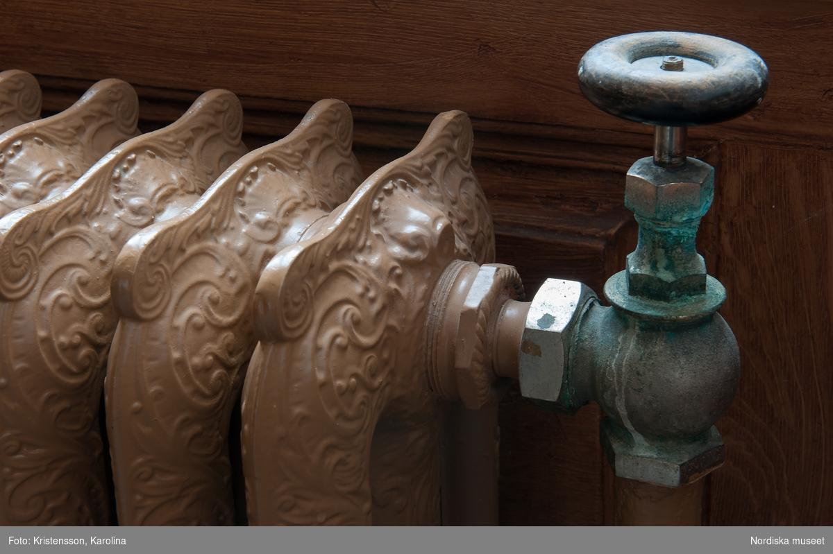
Freestanding cast-iron radiators for hot water heating have vertical sections that are interconnected at the top and at the bottom. These interconnections allow water to flow from one section to the next. Cast-iron radiators used for steam systems do not need to be interconnected at the tops, so they will not work if used for hot water heating. Older units have only two large tubes to carry the water from the top to the bottom of the section. In newer units, a section can have many small vertical pipes to perform this function. More pipes increase the surface area from which heat can be radiated.
Generally, the surface area of a section ranges from 0.09 m2 (1.2 ft) to 0.36 m2 (4.2 ft). Sections may be connected together by push nipples and bolts in a manner similar to cast-iron sectional boilers. Alternatively, the sections may be connected together by left- and right-hand nipples that have left- and right-hand threads at opposite ends. Left- and right-hand nipples can be tightened by turning them with a bar placed against the lugs within the nipple. This will pull the two sections together simultaneously. Gaskets are used as seals between the sections.
Freestanding radiators are typically 1 m (3 ft) high, 1 m (3 ft) or more long, and 125 mm to 200 mm (5–8 in.) wide; however, sizes may vary. They are well suited for window locations. In most cases, they are constructed to be no wider than a window in order to maximize the use of convection currents within the room.
Freestanding radiators take up a large amount of space. In addition, care must be taken to avoid obstructing these radiators with furniture. Also, because the radiators can be very hot, skin can burn on contact.
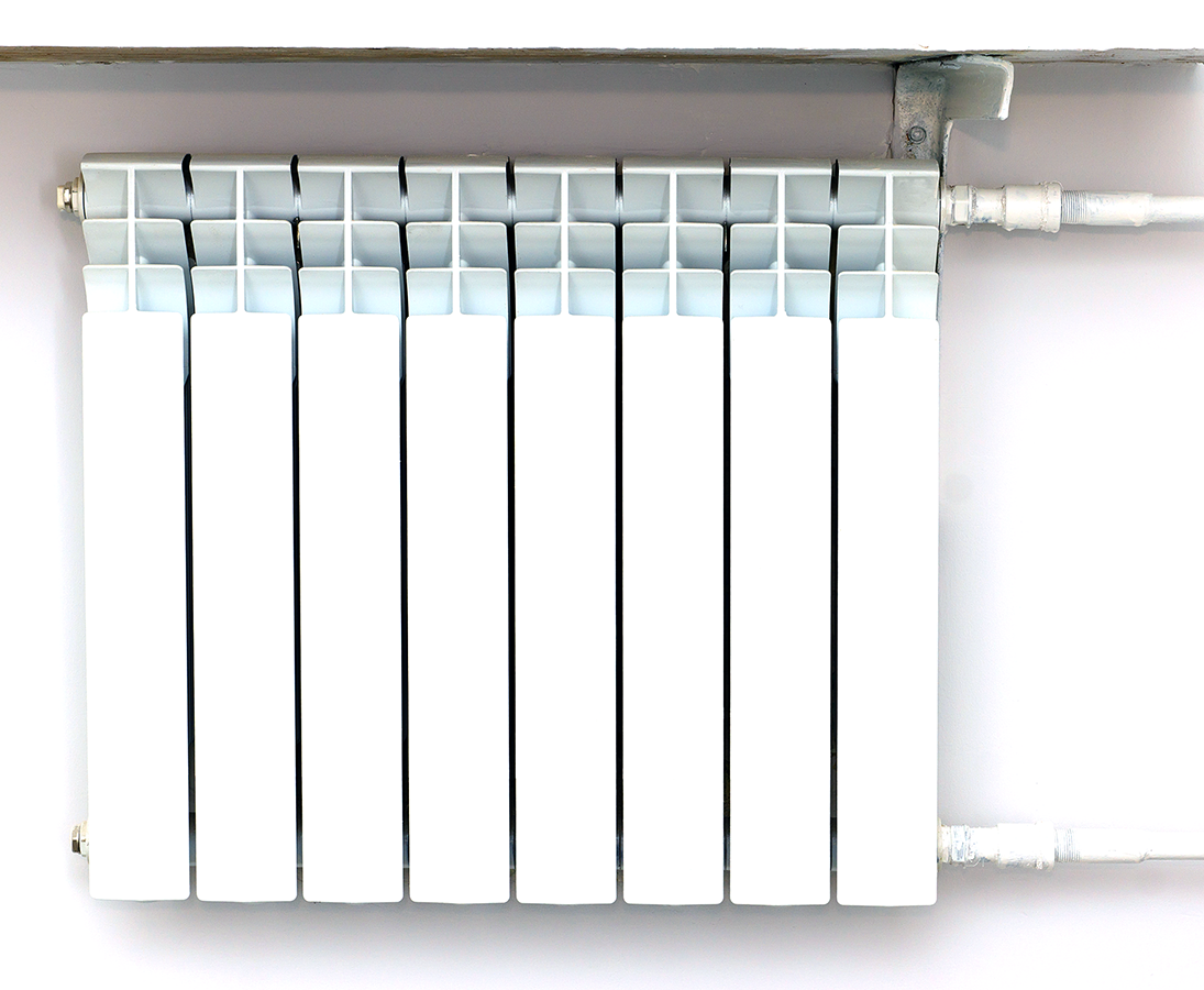
Radiant Baseboards
The large amount of space required for freestanding radiators prompted the innovation of cast-iron baseboard radiators. In a cast iron baseboard radiator (Figure 12), each section has a hollow core and is typically 0.3 or 0.6 m (1 or 2 ft) long and about 0.2 m (9 in.) high. Sizes may vary.
The sections are joined together by bolts and push nipples. Baseboard radiators are mounted on the outside walls, in the same manner as baseboard convectors. The end sections of a baseboard radiator have tappings (female threaded connections) for connecting supply and return piping.
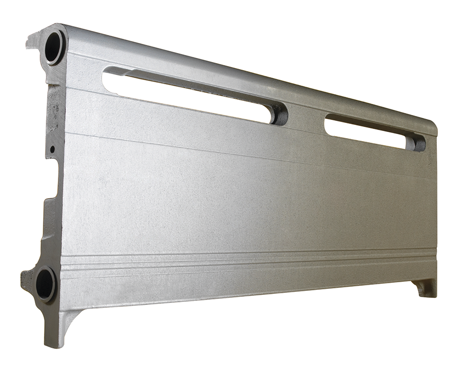
The main difference between a radiant baseboard and a finned tube baseboard is that a radiant baseboard contains no fins. Hot water runs through a copper tube within the housing, but rather than heating the air between the fins, it heats the front panel of the housing itself. This heat is then radiated to the objects in the room. Whereas, finned tube convectors do not radiate much heat because the front panel of the housing does not get hot. All the heat within it is trapped between the fins then moved out through convection currents.
Because baseboard units are long, they often extend beyond the dimensions of a window. As a result, there is warmth emitted along more of the cold outdoor wall. This brings a better balance of temperatures to all the cold surfaces of the room. The radiator-convector has air passages that promote some convection.
Panel Radiators vs. Radiant Panels
Although the names sound similar (in fact, there are many similarities between them), panel radiators are very different from radiant panels. Much literature has been written regarding both, and many times the words are used interchangeably. This text will differentiate between the two forms of transfer units.
Panel Radiators
Panel radiators (Figure 13) are factory-made in all shapes and sizes. Panel radiators are mostly constructed from steel, but some are made from aluminum. They contain tubing that circulates hot water, with the tubing pressed into channels in the back side of the panel. The tubing’s contact with the panel heats the panel via conduction, which, in turn, emits radiant heat outward into the room. Panel radiators are generally built to project their heat through radiation, but some are built to transfer their heat through convection as well. In that case, the radiator is manufactured to include fins, like a finned tube baseboard, which captures the heat then creates convection currents.
One of the benefits of panel radiators is the relatively small amount of wall or ceiling space they require. They are available in all shapes and sizes; a situation that could not fit a wallfin baseboard heater due to lack of space will likely accommodate a panel radiator. A good example would be in a kitchen, where wall space is limited.
Panel radiators generally do not contain much water or metal, so they have a low thermal mass. Thermal mass is the ability of a material to absorb and store heat. Heat transfer units with a low thermal mass are less likely to subject the occupants of a room to temperature overshoot.
Radiant Panels
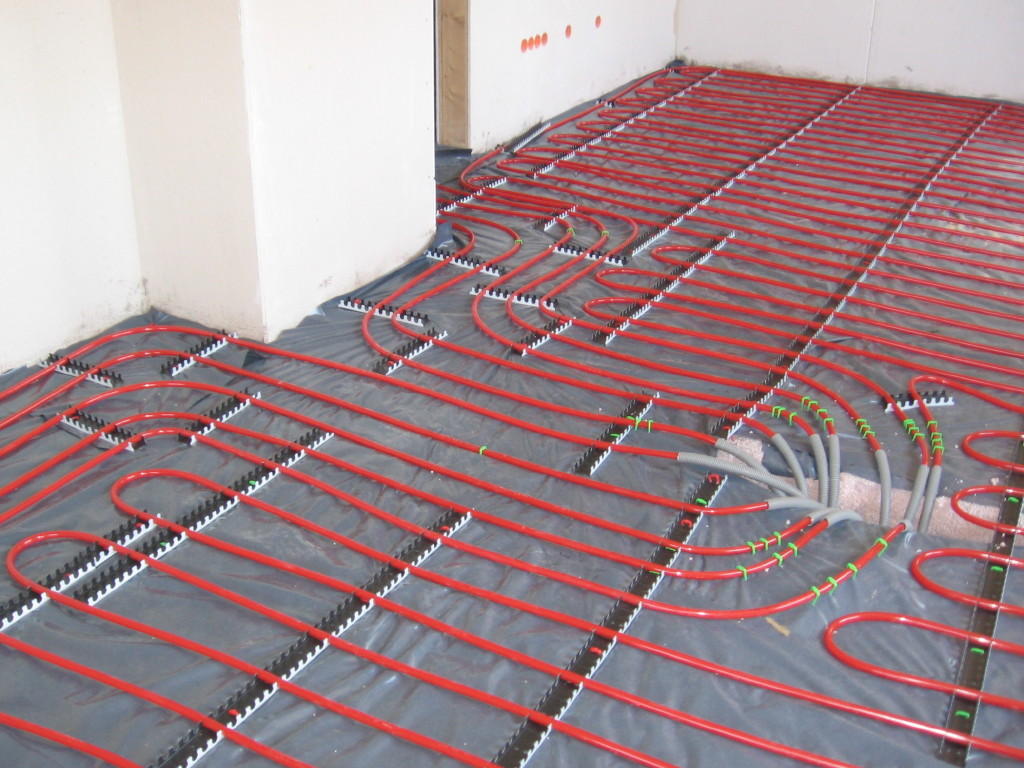
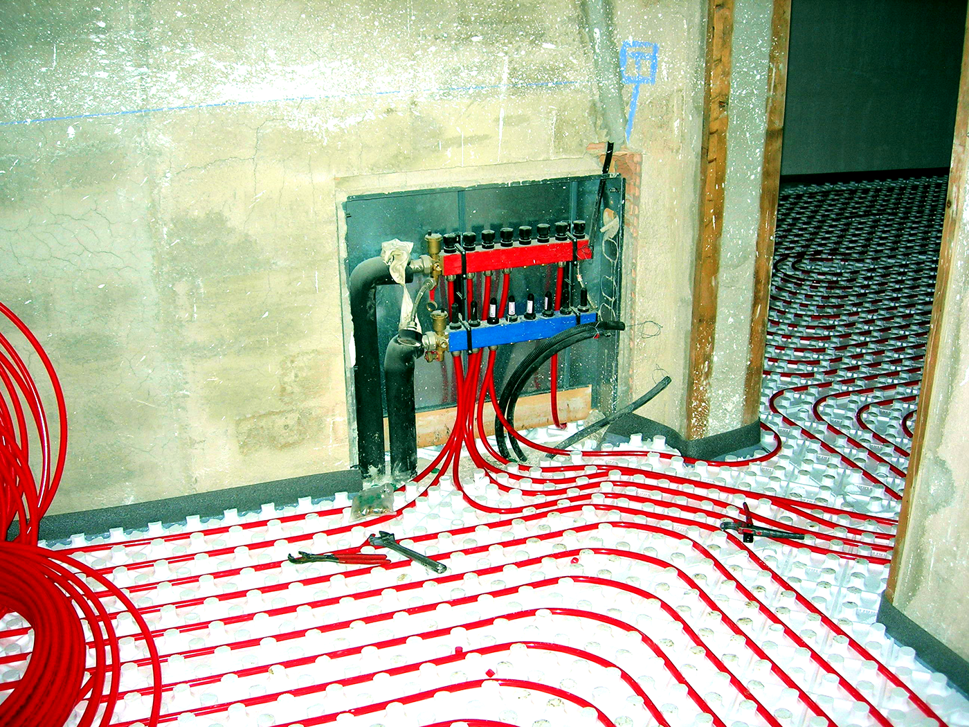
The phrase radiant panel most often refers to heating using the floor as a thermal mass, although there are also situations where either the ceiling or a wall can be used (Figure 14). There are a number of different methods of heating floors through radiant means, and the popularity of these types of systems is growing rapidly in North America.
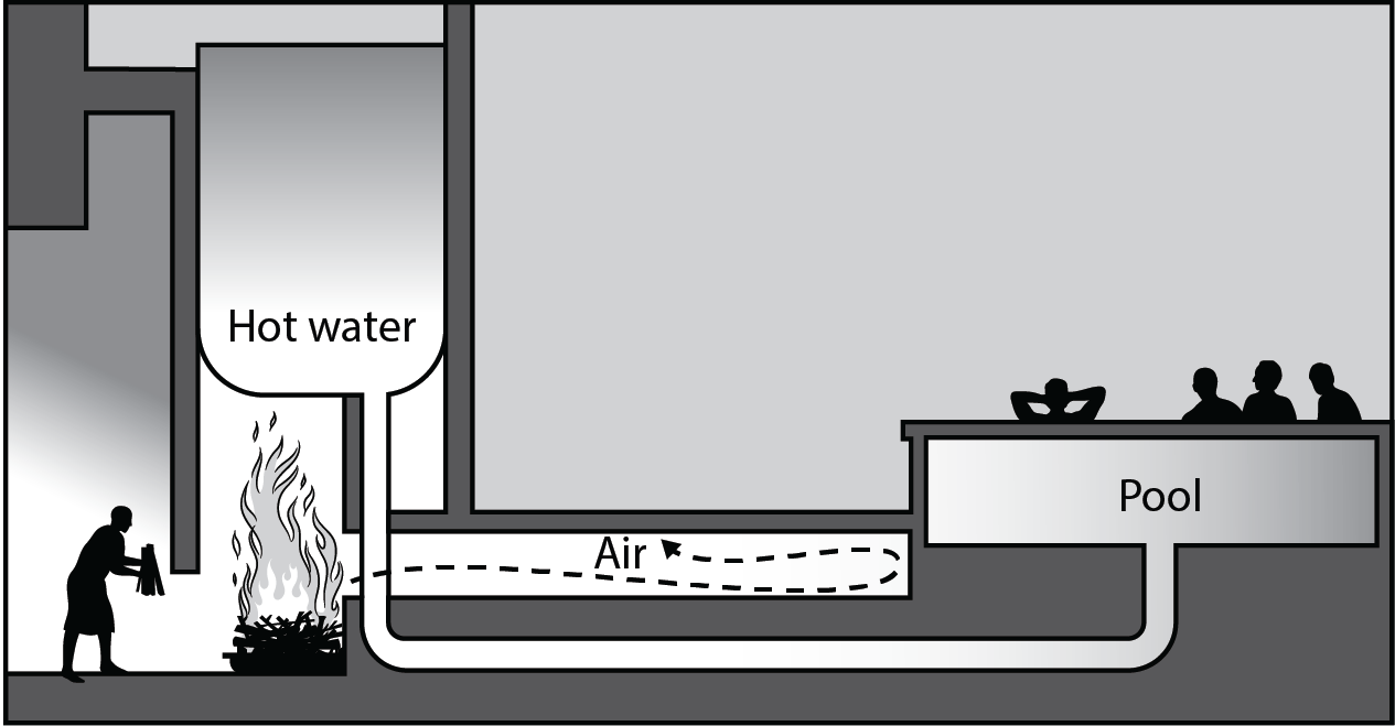
The practice of using the floor as a thermal mass has been around for thousands of years. Ancient Romans built hypocausts (Figure 15), which took combustion gases from wood fires and ran them underneath a stone floor. Many years later, with advances in technology, hot water was run through piping in the floor. The first piping material used for radiant floors was steel and wrought iron, but in the 1940s, the use of copper became popular. This continued until polybutylene was introduced in the mid-1970s. Polybutylene has since been replaced by cross-linked polyethylene, which is now the material of choice for radiant floor tubing.
Benefits of Radiant Panels
The main benefit of radiant floor panels is an increased level of comfort. A comfortable room is one in which the temperature “bands” in the room in a way that matches the human body’s requirements as closely as possible (Figure 16).
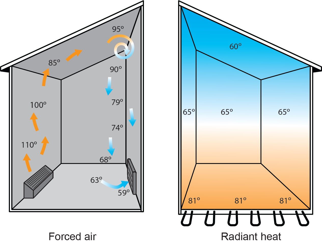
This is commonly referred to as the ideal heating curve (Figure 17). A room with this curve would be warmest at floor level (where you have contact with the surface), “comfortable” at eye level, and coolest near the ceiling (where not much heat is needed, in any case). The temperature of a “comfortable” room should be approximately 20°C to 22°C (68°F to 72°F) at eye level (approx. 1.5 m or 5 ft above the floor). A radiant floor panel system can deliver this.
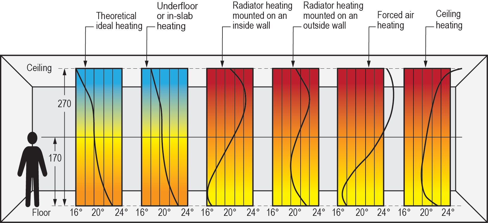
It is important to note that the curve representing forced-air heating is actually in direct conflict with or opposite to what the human body needs to feel comfortable.
Other benefits of radiant floor heating include:
- Does not use or waste interior space.
- Is durable and out of sight.
- Creates minimal drafts.
- Can be used with low-temperature heat sources.
- Can be used to dry floors in an area such as an airplane hangar or truck bay.
- Has a large thermal mass.
- Responds quickly to a loss of heated air such as when a door is opened.
- Has the ability to be “zoned.”
- Is the quietest of all heating systems.
Radiant panels can also provide hydronic cooling, but this application is limited to radiant ceiling panels. Circulating chilled water through tubing embedded in a floor would result in people becoming uncomfortable when walking on the floor. Again, hydronic cooling requires more elaborate control strategies to prevent condensation from forming on cool surfaces.
There are many methods of providing radiant heating, some of which include:
- Radiant floor panels
- Slab-on grade
- Gypsum thin slab
- Concrete thin slab
- Above floor and tube
- Below floor and tube
- Suspended tube
- Radiant walls
- Wall panel radiators
- Prefabricated radiant wall panels
- Site-constructed radiant wall panels
- Radiant ceilings
- Prefabricated radiant ceiling panels
- Site-constructed radiant ceiling panels
The choice of radiant system depends on many factors, not the least of which is installation cost. Other considerations include:
- Available floor space
- Intended floor coverings
- Amount of glass/doors in outside walls
- Building structural integrity
- Zoning preferences
- Heat source preferences
- Available height
The basics of radiant panel installations are all similar, regardless of which system is chosen. Heated boiler water is pumped through pipes installed on, in, or under the floor. The piping used in most of today’s installations is cross-linked polyethylene (PEX). The heat absorbed by the water is released through the walls of the PEX pipe as it travels through the radiant panel and then back to the boiler. It is important to note that the temperature of boiler water used in radiant floor systems is typically no higher than 49°C (120°F). This prevents both the floor and occupants from becoming too warm. Higher-temperature water is used in wall or ceiling panels to increase heat transfer rates, since these areas are usually out of reach and can be hotter.
Some radiant panel systems have the PEX tubing laid in concrete or gypsum (Figure 18). This is known as a “wet system.” The concrete or gypsum provides a thermal mass that acts like a big storage tank for heat, absorbing and retaining it. High thermal mass heat transfer units are generally slow to react to a change in temperature, but will hold their heat longer than low-mass units.
 Self-Test B-3.1: Hydronic Heat Transfer Units
Complete the chapter Self-Test B-3.1 and check your answers.
If you are using a printed copy, please find Self-Test B-3.1 and Answer Key at the end of this section. If you prefer, you can scan the QR code with your digital device to go directly to the interactive Self-Test.

References
Skilled Trades BC. (2021). Book 1: Fuel gas systems, Heating and cooling Systems. Plumber apprenticeship program level 2 book 1 Harmonized. Crown Publications: King’s Printer for British Columbia.
Trades Training BC. (2021). B-3: Install hydronic transfer units. In: Plumber Apprenticeship Program: Level 2. Industry Training Authority, BC.
Media Attributions
All figures are used with permission from Skilled Trades BC (2021) unless otherwise noted.
- Figure 11 Tyresö slott, interiör, detaljer by Karolina Kristensson, via DigitaltMuseum, is used under a CC BY-NC-ND 4.0 license.
- Figure 14 Underfloor heating pipes by H. Raab (User:Vesta), via Wikimedia Commons, is used under a CC BY-SA 3.0 licence.
- Figure 18 Col·lector terra radiant i tubs by Chixoy, via Wikimedia Commons, is used under a CC BY-SA 3.0 liense.
Steam heating systems use convectors, cast-iron radiators, wall fin tubes, and similar heat-emitting units. (Section B-1.4 and Section B-3.1)
Heating devices installed along the baseboards of rooms. They use electricity or hot water to produce heat, which is then radiated into the room. These units are effective for heating spaces efficiently and are often controlled by thermostats to maintain desired temperatures. (Section B-3.1)
Heating devices that are installed in ceilings, walls, or floors of buildings. They emit infrared radiation, which directly heats objects and people in the room without heating the air. This method of heating is efficient and provides comfortable warmth evenly throughout the space. (Section B-3.1)
A type of window or vent with slats that can be moved or tilted. These slats can be adjusted to control the amount of light, air, and noise that comes through, making them useful for ventilation and privacy. (Section B-3.1)
The exhaust gases produced from combustion processes, such as those in furnaces, boilers, or industrial equipment. These gases are typically very hot and contain by-products of combustion such as carbon dioxide, water vapor, carbon monoxide, and other pollutants. Hot flue gases are often directed through flues or exhaust pipes to safely remove them from the combustion chamber or heating system. They may also be used in heat exchangers to recover some of their thermal energy before being vented to the atmosphere. (Section B-3.1)
A unit that uses circulating water to heat or cool air by passing it over coils, adjusting the room temperature efficiently. (Section B-3.1)
