B-1.2 Low-Pressure Steam Heating Systems
A steam heating system takes advantage of the high latent heat given off when steam condenses to water. Although residential steam heating systems were very common in the late 19th and early 20th centuries, they are rarely installed in new single-family residential construction. Compared to other heating methods, it is more difficult to control the output of a steam system.
However, steam can be sent to places (e.g., between buildings on a college or university campus), which allows an efficient central boiler and low-cost fuel to be used. Tall buildings take advantage of steam’s low density to avoid the excessive pressure required to circulate hot water from a basement-mounted boiler. In industrial systems, process steam used for power generation or other purposes can also be tapped for space heating. Steam for heating systems may also be obtained from heat-recovery boilers using otherwise wasted heat from industrial processes.
In a steam heating system, each room is equipped with a radiator, which is connected by piping to a steam boiler. Steam entering the radiator condenses and gives up its latent heat, and the radiator, in turn, heats the room or zone. The condensate water (or condensate) returns to the boiler either by gravity or with the assistance of a pump. Some systems only use a single pipe for combined steam and condensate return. Since trapped air prevents proper circulation, such systems have vent valves to allow air to be purged. Pipes must be carefully sloped to prevent trapped condensate blockage. In domestic and small commercial buildings, the steam is generated at relatively low pressure, less than 15 psig (200 kPa).
Latent heat, not steam pressure, does the actual heating work in a residential steam heating system. Remember that steam gives up 970 BTU of usable heat for every pound that condenses back to water. The job of steam pressure is strictly to overcome the friction that steam meets as it works its way around the system. A steam heating system requires only enough pressure back at the boiler to overcome the system piping’s friction; that pressure is very low because the pipe is sized to offer very little resistance to steam flow. Therefore, house steam heating systems should not operate at pressures higher than two psig.
Steam heating piping systems are classified by how they handle the steam and condensate. One-pipe systems use common piping for both the steam and condensate, whereas two-pipe systems use separate piping for each.
System Components
The following is a list of some more common components found in low-pressure steam heating systems, some of which are shown in Figure 1.
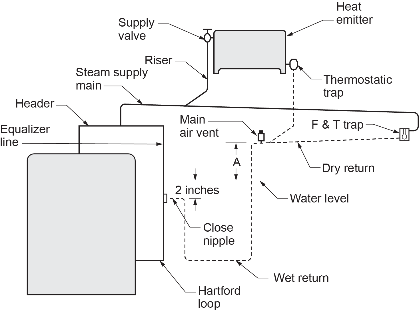
Steam boiler: Steam boilers differ from hot water boilers in that they are only partially filled with water. A sight glass is provided for visual observation of the boiler water level. A relief valve protects the boiler from damage should excessive pressures occur. The burner is operated from a steam pressure switch, called a pressuretrol, which determines the operating pressure range of the boiler. During a call for heat, the boiler will cycle up to the cut-out setting of the pressuretrol. At that point, the pressuretrol will shut off the burner. Commercial boilers also require a manual-reset high-limit pressuretrol to shut off the burner should the pressure rise too high.
Header: Boilers, depending upon their size, have one or more outlet tappings. The vertical steam piping from the tapped outlet joins a horizontal pipe called a header. The steam supply mains are connected to this header. If the boiler has more than one outlet, it is important to remember to pipe the headers with swing joints. This will help alleviate any stress on the boiler when the header heats up and expands.
Equalizer line: The equalizer line is the vertical piping at the end of the header going back to the boiler return connection. Its job is to return any water that slips out of the boiler with the steam and to balance the pressure between the supply and the return sides of the boiler. Without a properly sized equalizer, water can back out of the boiler.
Steam supply main: The steam supply main carries steam from the header to the radiators connected along its length.
Risers: The vertical pipe carrying steam to the radiator from the supply main is called a riser.
Heat emitters (units): Steam heating systems use convectors, cast-iron radiators, wall fin tube, and similar heat-emitting units.
Dry return: The dry return is the portion of the return main located above the boiler water level.
Wet return: The wet return is the portion of the return main located below the boiler water level. It is always completely filled with water and does not carry air or steam in the same way that the dry return does.
Hartford loop: The Hartford loop is a piping arrangement designed to prevent complete drainage of the boiler should a leak develop in the wet return. The wet return is connected to an equalizing line between the supply and return opening of the boiler. This connection is made about 2 in. below the normal water level of the boiler. This connection between the loop and the equalizer must be made with a close nipple to prevent water hammer.
Gauge glass: The gauge glass is used to identify the water level in the boiler. Expect to see some minor movement in the water line when the boiler is operating. When the boiler is off, the “normal” water line is the centre of the gauge glass. When the system is running, the “normal” water line is near the bottom of the gauge glass.
Air vents: Steam cannot circulate, nor can radiators emit heat until air has been vented from the system. Thermostatic air vents are installed on each radiator and at the end of each steam main. Thermostatic steam traps also act as air vents.
Radiator valves: Radiator valves control the steam supply to the system radiators. Each radiator is equipped with an angle pattern radiator supply valve.
Steam traps: Steam traps prevent steam from getting into the condensate returns because they close in the presence of steam creating a separation from the return piping of the system. The steam trap has three jobs — to let air pass through the radiators, to close when steam reaches it, and to open when condensate accumulates.
Relief valve: The relief valve protects the boiler against a runaway fire. On space-heating steam boilers, the relief valve is set to pop open and relieve pressure at 15 psi. This is the limit for any low-pressure boiler.
Low-water cut-off: The job of the low-water cut-off is to shut off the burner should the water level fall to an unsafe level. The boiler manufacturer determines this level, but it is usually within one-half inch of the bottom of the gauge glass.
One-Pipe Steam Systems
One-pipe systems take their names from the single pipe that connects each radiator to the steam main. Both steam and condensate travel in this pipe but in opposite directions.
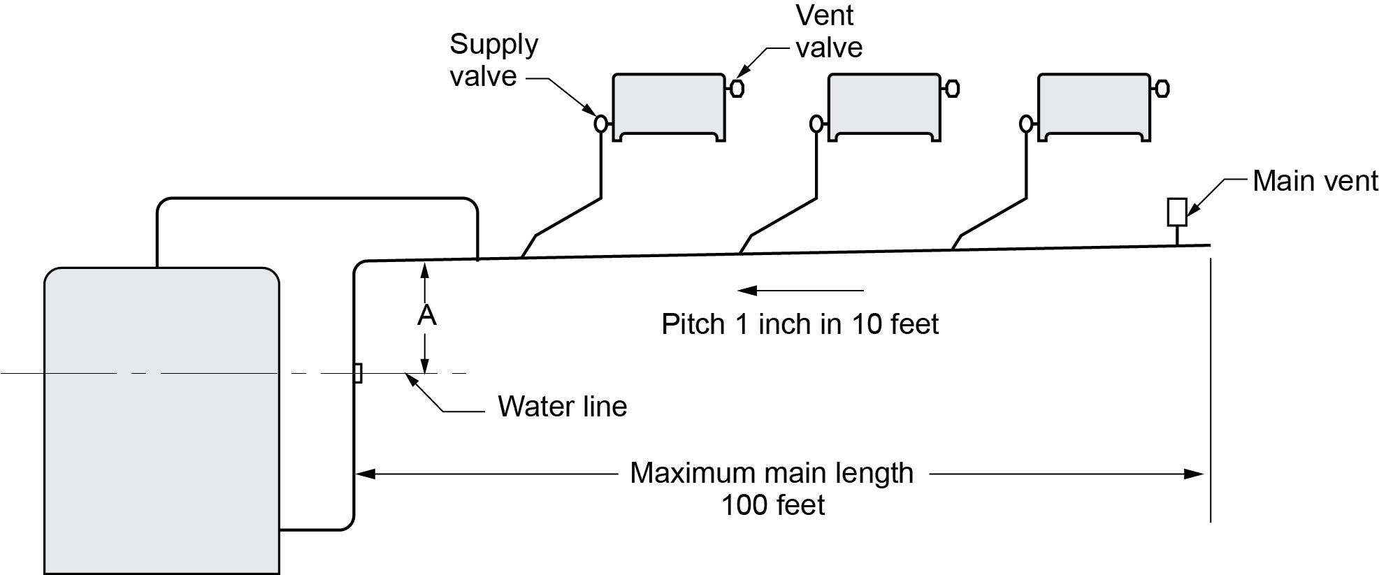
Counterflow System
In counterflow systems (Figure 2), the steam and condensate travel in opposite directions in the steam main piping. When there is counterflow, the pitch must be at least 1 in. in 10 ft. The steam main must be one size larger than one used for other types of one-pipe systems.
Dimension A (Figure 2) must be of sufficient height to provide enough gravity head pressure to return condensate to the boiler. The head provided by the height of this column consists of the steam system pressure drop and the static head needed to overcome the pressure drop in the condensate return lines. It is standard practice for a system based on [latex]\tfrac{1}{2}[/latex] psi pressure drop to make the minimum distance for Dimension A not less than 28 in.
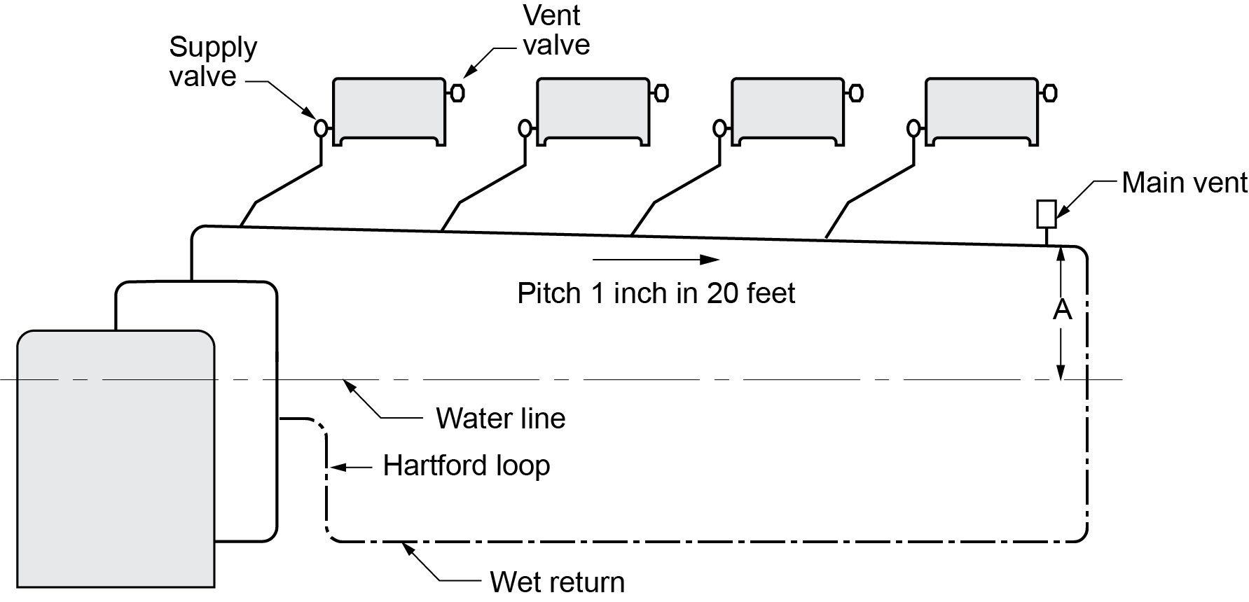
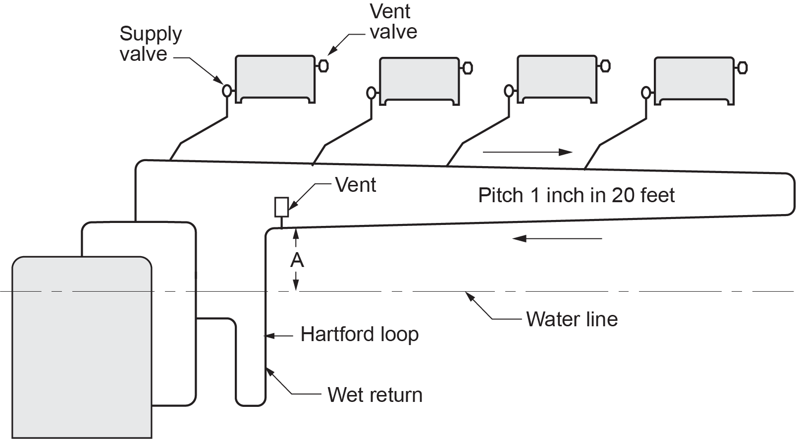
Parallel Flow System
In parallel flow systems, the steam and condensate move in the same direction in the horizontal steam and return mains. The pitch on the mains should be at least 1 in. in 20 ft. Figure 3 shows a parallel flow system with a wet return from the end of the steam main, and Figure 4 shows a dry return.
Two-Pipe Steam Systems
Two-pipe systems (Figure 5) differ from one-pipe systems in that the former carries steam and condensate to and from the radiators using separate lines. The steam lines supply steam to the radiators, which discharge their air and condensate to the return lines. Traps are used at each radiator and at the end of each supply main to prevent the entry of steam into the return lines.
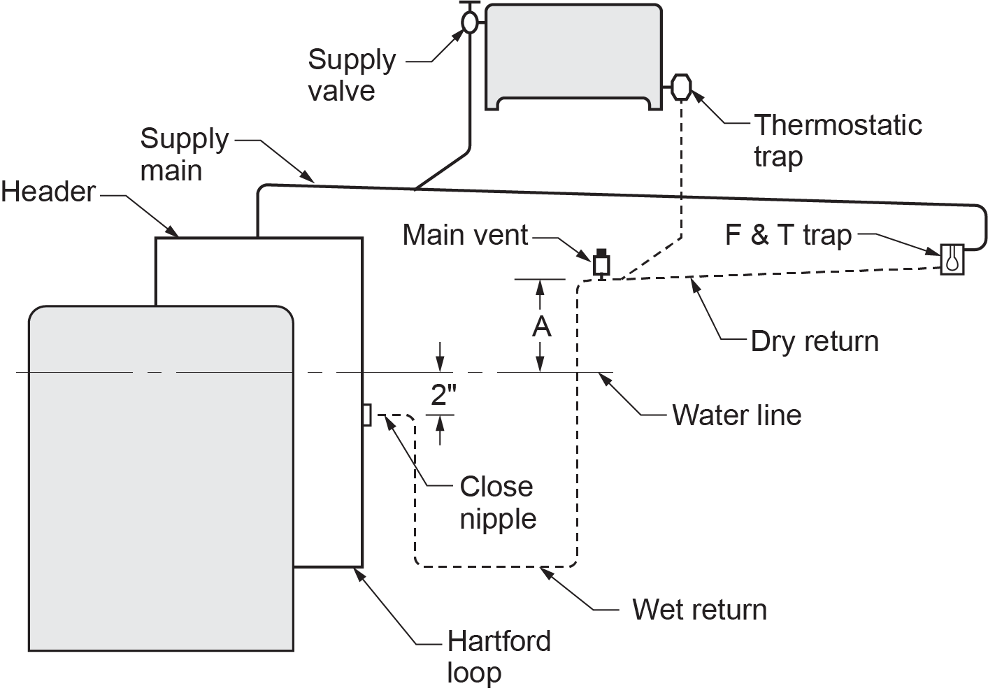
Steam traps also have a curious effect on the system’s returns. Because they close off the steam, traps prevent steam pressure from getting into the returns. In a one-pipe system, the water returns to the boiler because of the static weight of the water in Dimension A and the “leftover” steam pressure at the end of the main.
Two-pipe systems do not have any leftover steam pressure to help move the condensate back into the the boiler. This is because of the traps. This means that with two-pipe steam systems, Dimension A must be at least 30 in. for every pound of pressure in the boiler. In other words, if a boiler fires at 2 psig, it will need 60 in. of height between the centre of the gauge glass and the bottom of the lowest steam main.
This is why condensate pumps are often used in two-pipe steam systems.
Pumped Condensate Return Systems
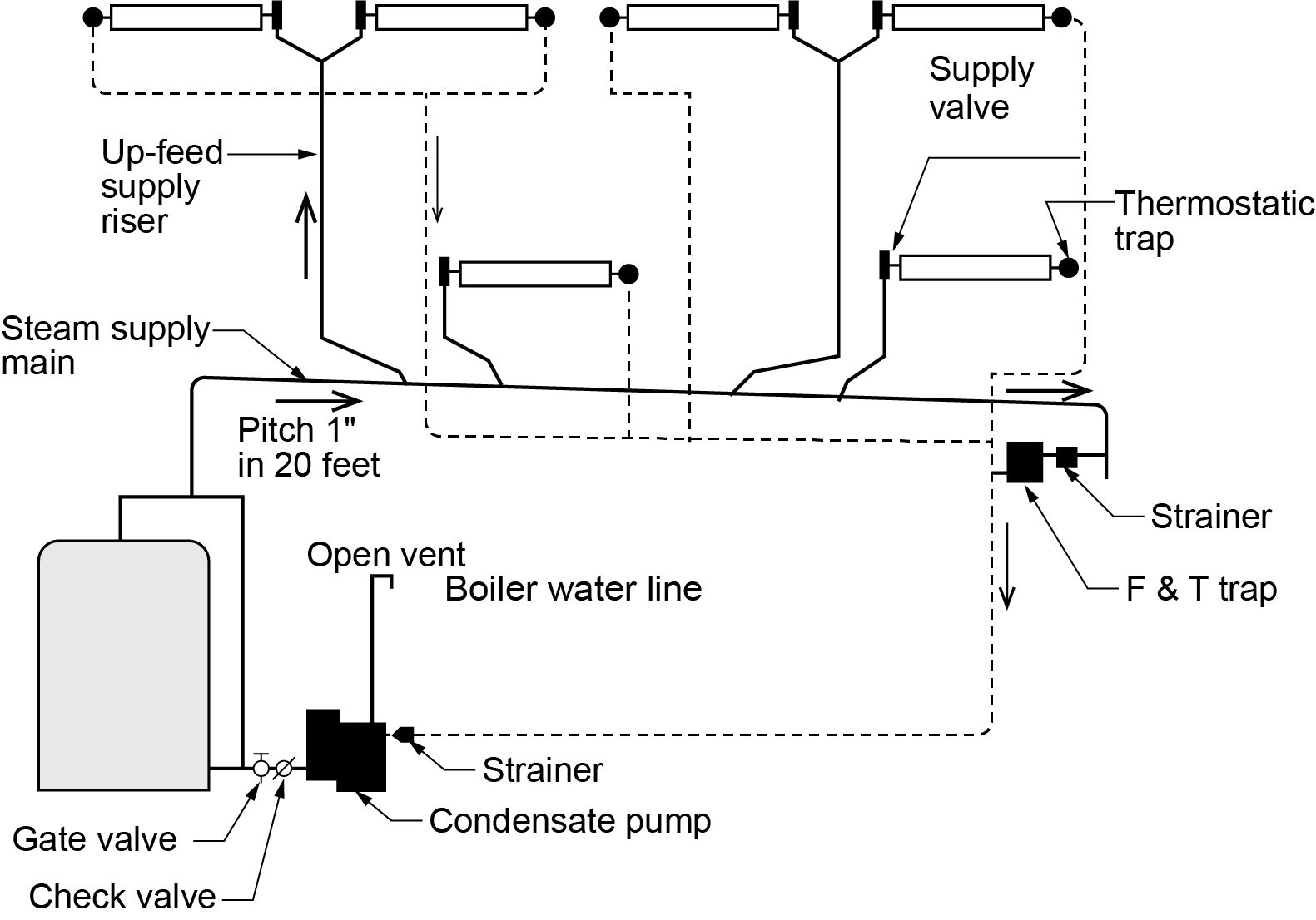
Installations with their dry return at an insufficient elevation over the boiler water line to provide gravity condensate return must be equipped with condensate return pumps (Figure 6). A condensate pump is the low point in the system. Everything must flow downhill to it. A condensate pump has a receiver tank for collecting returning condensate; the tank is vented to the atmosphere.
Inside the receiver is an electrical float switch. This switch turns the pump on when the water level inside the receiver rises and off when it falls. On the discharge side of the pump is a check valve (to keep the boiler water in the boiler) and a throttling valve. The throttling valve is used to slow the pump down because most pumps discharge at too high a rate and pressure for most residential heating applications. The throttling valve will stop the check valve from chattering by adding resistance to the pump’s pressure.
One problem with condensate pumps is that they are only designed to fill and dump. They have no way of detecting if the boilers they serve need water or not, which can be a problem for low-water-content boilers. Because of this, boiler-feed pumps are sometimes used in place of condensate pumps.
A boiler-feed pump is different from a condensate pump because the float switch that controls the pump is located on the boiler itself rather than in the pump’s receiver. With a boiler-feed pump, the pump can come on only if the boiler needs water.
The receiver in the boiler-feed pump is also much larger than the condensate pump’s receiver. This oversized receiver gives the condensate a place to wait until the boiler needs it.
 Self-Test B-1.2: Low-Pressure Steam Heating Systems
Complete Self-Test B-1.2 and check your answers.
If you are using a printed copy, please find Self-Test B-1.2 and Answer Key at the end of this section. If you prefer, you can scan the QR code with your digital device to go directly to the interactive Self-Test.

References
Skilled Trades BC. (2021). Book 1: Fuel gas systems, heating and cooling systems. Plumber apprenticeship program level 2 book 1 (Harmonized). Crown Publications: King’s Printer for British Columbia.
Trades Training BC. (2021). B-1: Describe types of heating and cooling systems. In: Plumber Apprenticeship Program: Level 2. Industry Training Authority, BC.
Media Attributions
All figures are used with permission from Skilled Trades BC (2021) unless otherwise noted.
A steam boiler is a device that heats water until it turns into steam. This steam is then used to provide heat or power. It works by burning fuel like coal, oil, or gas, or by using electricity to generate heat. The steam produced can be used for various purposes, such as heating buildings, running engines, or powering machines. (Section B-1.2)
Note: Steam boilers differ from hot water boilers because they are only partially filled with water. They have a sight glass for checking the water level and a relief valve to prevent damage from excessive pressure. A pressure switch, or pressuretrol, controls the burner and determines the boiler's operating pressure. When heat is needed, the boiler runs until it reaches the pressuretrol's cut-out setting, then the pressuretrol shuts off the burner. Commercial boilers also have a manual-reset high-limit pressuretrol to turn off the burner if the pressure gets too high.
Boilers, depending upon their size, have one or more outlet tappings. The vertical steam piping from the tapped outlet joins a horizontal pipe called a header. The steam supply mains are connected to this header. If the boiler has more than one outlet, it is important to remember to pipe the headers with swing joints. This will help alleviate any stress on the boiler when the header heats up and expands. (Section B-1.2 and Section B-4.2)
An outlet tapping is when a hole is made in a pipe to add another pipe or valve. This lets water or gas flow from the main pipe to a new area, like a faucet or another system. (Section B-1.2)
The vertical piping at the end of the header going back to the boiler return connection. Its job is to return any water that slips out of the boiler with the steam, and to balance the pressure between the supply and the return sides of the boiler. Without a properly-sized equalizer, water can back out of the boiler. (Section B-1.2 and Section B-4.2)
The steam supply main carries steam from the header to the radiators connected along its length. (Section B-1.2)
A vertical pipe or duct that carries water, steam, air, or other fluids up through different floors of a building. It's used to move fluids between different levels or stories in a building. (Section B-1.2, Section B-4.1, and Section B-4.4)
Steam heating systems use convectors, cast-iron radiators, wall fin tubes, and similar heat-emitting units. (Section B-1.4 and Section B-3.1)
The dry return is the portion of the return main located above the boiler water level. (Section B-1.2)
The portion of the return main, located below the boiler water level. It is always completely filled with water and does not carry air or steam in the same way the dry return does. (Section B-1.2)
A piping arrangement designed to prevent complete drainage of the boiler if a leak develops in the wet return. The wet return is connected to an equalizing line between the supply and return opening of the boiler. This connection is made about 2” below the normal water level of the boiler. This connection between the loop and the equalizer must be made with a close nipple to prevent water hammer. (Section B-1.2)
Used to identify the water level in the boiler. Expect to see some minor movement in the water line when the boiler is operating. When the boiler is off, the “normal” water line is the centre of the gauge glass. When the system is running, the “normal” water line is near the bottom of the gauge glass. (Section B-1.2)
Steam cannot circulate nor can radiators emit heat until air has been vented from the system. Thermostatic air vents are installed on each radiator and at the end of each steam main. Thermostatic steam traps also act as air vents. (Section B-1.1, Section B-3.1 and Section B-3.2)
Radiator valves control the steam supply to the system radiators. Each radiator is equipped with an angle pattern radiator supply valve. (Section B-1.2 and Section 4.2)
Steam traps prevent steam from getting into the condensate returns, because they close in the presence of steam, creating a separation from the return piping of the system. The steam trap has three jobs: to let air pass through the radiators, to close when steam reaches it, and to open when condensate accumulates. (Section B-1.2)
These valves protect the boiler against a runaway fire. On space-heating steam boilers, the relief valve is set to pop open and relieve pressure at 15 psi. This is the limit for any low-pressure boiler. (Section B-1.2, Section B-4.1, and Section B-4.2)
The job of the low-water cut-off is to shut off the burner should the water level fall to an unsafe level. The boiler manufacturer determines this level, but it is usually within one-half inch of the bottom of the gauge glass. (Section B-1.2 and Section B-2.1)
A term used to describe a situation where two substances, such as fluids or gases, flow in opposite directions relative to each other. This arrangement maximizes the efficiency of heat or mass transfer between the substances by allowing the greatest temperature or concentration difference across the exchange interface. (Section B-1.2)
