B-4.2 Hydronic System Valves
There are many types of valves used in hydronic systems. Most of these valves are common to other piping trades and can be found in plumbing, sprinkler fitting, and steam fitting systems. Others are designed for a very specific function in a hydronic heating system. The proper use of valves can make the difference between an efficient, quiet, and easily serviced hydronic system, and one that wastes energy, creates objectionable noise, or even poses a major safety threat.
Common Valves
Most common valves are designed for either component isolation or flow regulation.
Component isolation refers to the use of a valve to stop fluid flow in piping connected to a device that may have to be removed or opened for servicing. Examples include circulators, boilers, heat exchangers, pumps, and strainers. By placing valves on either side of such components, only minimal amounts of system fluid need to be drained or spilled during servicing. In many cases, other portions of the piping system can remain in operation during such servicing.
Flow regulation requires a valve to set and maintain a given flow rate within a piping system or portion thereof. An example is adjusting the flow rates in parallel piping branches to heat emitters.
Valves used for flow regulation are specifically designed to remove mechanical energy from the fluid. This causes the fluid’s pressure to drop as it passes through the valve. The greater the pressure drop, the slower the flow rate through the valve.
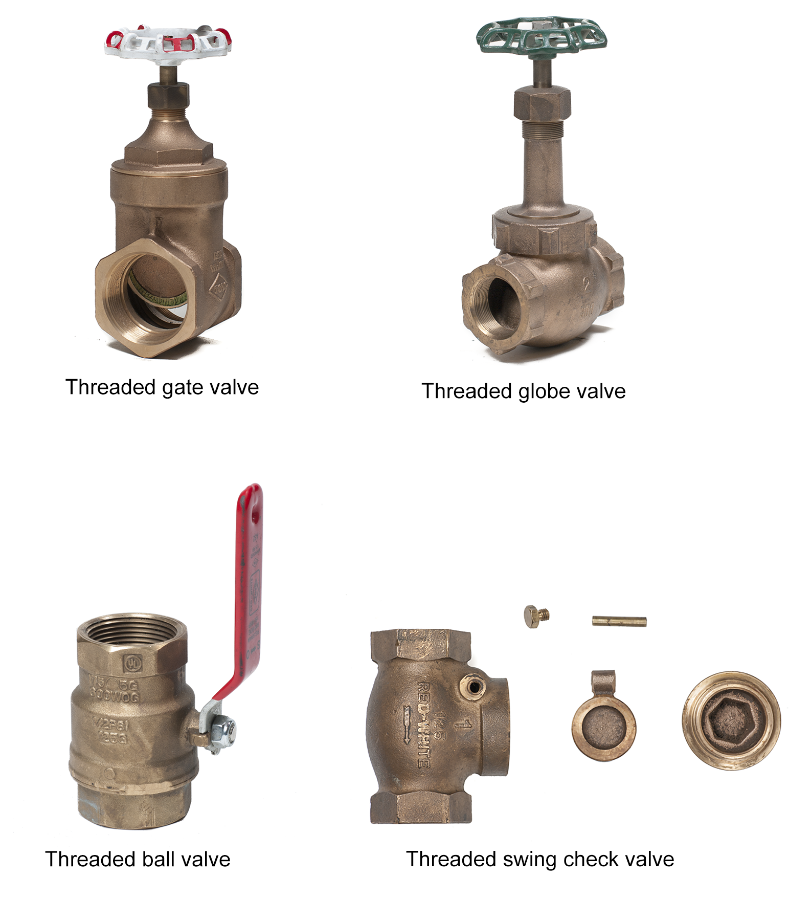
Valves commonly used in hydronic piping systems (Figure 1) include the following:
- Gate valves
- Globe valves
- Ball valves
- Check valves
Gate, globe, and ball valves are all examples of manual valves that can be used for isolation. Air will flow easily through an open gate or ball valve. Because of their restrictive interior design, globe valves are limited to being used to provide throttling or isolation on feedwater lines. The globe valves are also modified into a specialty valve called a balancing valve. These are used for throttling flows in a hydronic system. Check valves can be used wherever reverse flow is unwanted.
Specialty Valves
Several valves have very specific functions in hydronic systems. Some provide safety protection, some are required by code, and others automatically regulate the temperature and pressure at various points in the system. All these valves will be incorporated into systems discussed in later phases of training.
Pressure Relief Valves
All closed-loop hydronic systems must be protected by a pressure relief valve. Its function is to provide a relatively controlled and safe release of water in the event of excessive pressure in the system.
Pressure relief valves are designed and labelled to open at a specific pressure. In systems with boilers, the relief valve is threaded directly onto the boiler or a nearby supply pipe.
Pressure within a hot-water heating system could reach dangerous levels through the failure of a component to shut off the burner or a failure within the water makeup system. Installing the correct pressure relief valve will prevent pressure from building up to an unsafe or dangerous level.
The pressure relief valve for a hot-water heating boiler is spring-loaded and opens at a pressure that is preset at the factory. The valve must not have a discharge pressure setting greater than the maximum rated pressure of the boiler. The pressure relief valve must be capable of discharging as much heat as the boiler can produce. This means that the relieving capacity must match or exceed the output rating of the boiler. An extra margin of safety is given if the boiler’s input, rather than its output, is used in selecting the relief valve capacity.
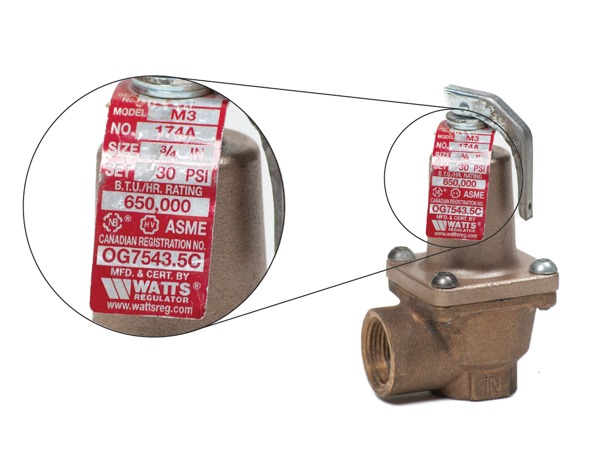
Every pressure relief valve has an information or rating plate (Figure 2) that identifies the following:
- The relief pressure setting; for example, 210 kPa (30 psi)
- The relieving capacity; for example, 44 kW (150,000 BTU)
- The size of the valve; for example, [latex]\tfrac{3}{4}[/latex] NPS
The pressure relief valve must be installed directly on the boiler, and there may not be any other valve between the pressure relief valve and the boiler. The spring-loaded valve of the pressure relief valve opens when the preset pressure is reached. When the pressure within the boiler drops sufficiently, the valve closes.
The pressure is relieved by discharging water through a pipe to a drain or safe location. The piping used for the outlet must be:
- The same size as the pressure relief valve
- No more than 300mm (12″) from the floor
- Sloped down and away from the valve to prevent a buildup of back pressure
If the pressure relief valve drips water from its discharge opening, and the pressure indicated is not close to the opening pressure of the valve, there may be some debris in the valve seat. To flush the valve, stand in a position clear of the valve’s discharge opening. If the boiler temperature is high, scalding water or steam will be discharged. Open the valve fully for a moment to flush out the valve seat and let a finger slide off the end of the trip lever so that it slams shut to prevent nuisance dripping.

If this does not stop the dripping, the valve has failed and must be replaced. Make sure the replacement valve is of the same type and has the same opening pressure and heat relief capacity. Never plug, cap or install a valve on the discharge side of the pressure relief valve.
If the valve drips because the pressure in the system is at its maximum, the valve is doing its job, and the cause of the excess pressure must be found and fixed.
If the information tag is missing from the pressure relief valve, the valve must be replaced because the correct safe discharge pressure setting cannot be determined.
Boiler Water Makeup
Water makeup refers to the piping and accessories connected to the system that not only fill it, but maintain a constant pressure within it. It’s important to carefully select the connection to the system piping. Cold water should never be added directly to a hot boiler, as this can cause thermal shock and crack the metal. Instead, the water makeup is normally introduced into the hot supply main from the boiler through the same fitting used to connect the expansion tank, which is the point where pressure remains stable.
The water makeup to a boiler has four components:
- Main stop valve
- Backflow preventer
- Feedwater valve (pressure-reducing valve)
- Bypass valve (quick fill)
Main Stop Valve
The main stop valve is normally a ball or gate valve; in other words, a valve that, in operation, is either open or closed. Although almost any manual valve will perform the intended function, ball valves are used most often because they are readily available and easily seen as either open or closed. The position of a valve with a rotary handle, such as a gate or globe valve, cannot be seen at a glance as being open or closed and so they are less commonly used.
Backflow Preventer
As seen above, water is introduced into the hydronic system through the feedwater or pressure-reducing valve. Once in the hydronic system, this water is no longer considered part of the domestic system, and there must be some mechanism that ensures boiler water does not return to the domestic system and contaminate it.
A backflow preventer performs this function. A backflow preventer does exactly as the name implies: it prevents the flow of liquid back to where it originated. All boiler systems require a backflow preventer. The type and style of backflow preventer are determined by the presence or absence of additives in the boiler water and whether it is a residential or commercial installation. A typical backflow preventer on a residential hydronic system is a dual check with an atmospheric port (Figure 3).
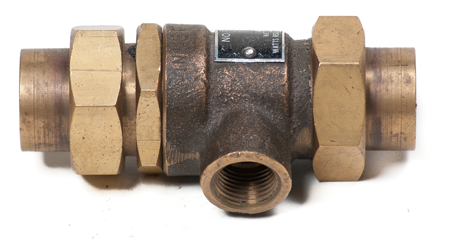
This device has two check valves in series, with a port open to atmosphere located between the two check valves. If water flows in the opposite direction than intended, it will be discharged through the atmospheric port to the atmosphere.
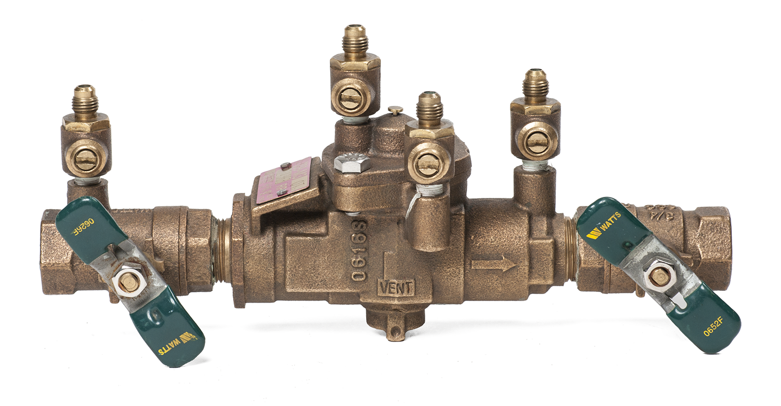
If chemicals have been added to the boiler system, in many jurisdictions, a more reliable backflow preventer must be installed. An example is the reduced pressure backflow assembly (Figure 4), which functions similarly to a dual check with an atmospheric port but with the added advantage of being in-line testable. Testing the assembly regularly ensures its proper operation.
Feedwater Valves
All hydronic systems referred to in this section are known as closed-loop systems. Even though they are closed loop, they still require the ability to fill the system and have water added when necessary. This is done automatically through a feedwater valve, also known as a pressure-reducing valve (Figure 5).
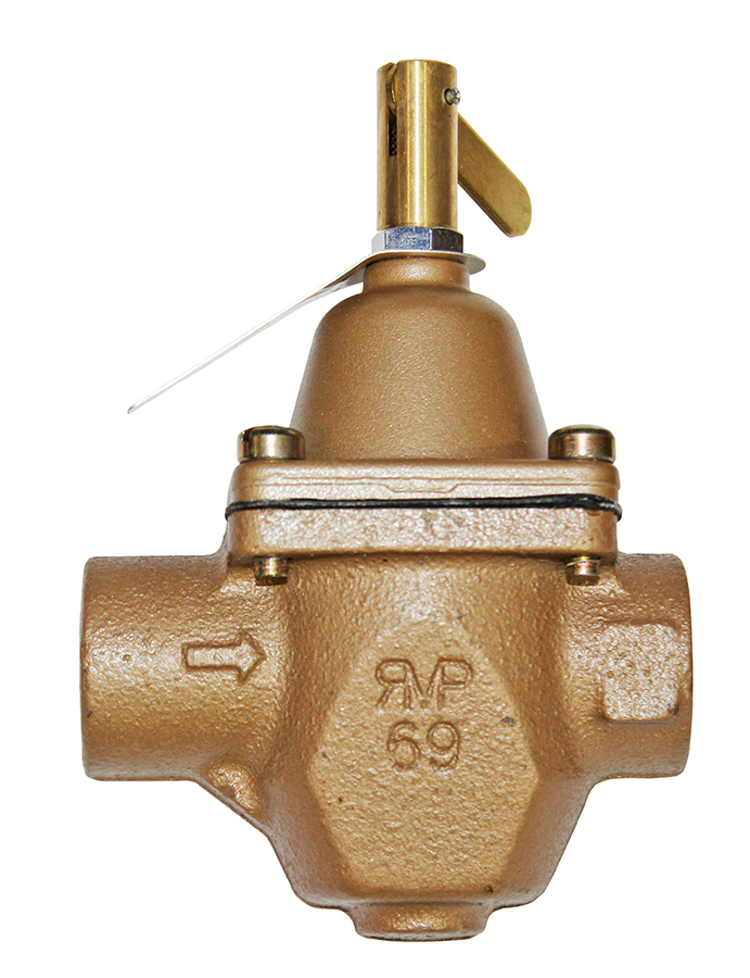
A feedwater valve takes the domestic water from the building and lowers the pressure to the working pressure of a hydronic heating system before it enters the system. For a residential system, this pressure is normally between 12 psig (84 kPa) to 20 psig (140 kPa). A hydronic system will typically lose a little water due to air being eliminated as the system goes through its cycles. Potable water is brought in through the feedwater valve when the valve senses the pressure in the system has dropped below its pre-set level. Once enough water has been introduced into the system to bring it to its operating pressure, the feedwater valve automatically closes and no more water is added.
Bypass (Quick-Fill)
Some feedwater valves, like the one shown in Figure 5, have a lever at the top that allows the valve to be manually opened to quickly fill the system during startup. When lifted, this lever temporarily disables the pressure-regulating function of the valve and is known as a bypass. The lever must be manually returned to its normal position after the system is filled and purged (bled of air).
The bypass feature supplies the system with full building pressure to rapidly fill the system. Furthermore, the velocity of water entering the piping helps push air out of purge valves for better initial air removal (see “purge valve” description below).
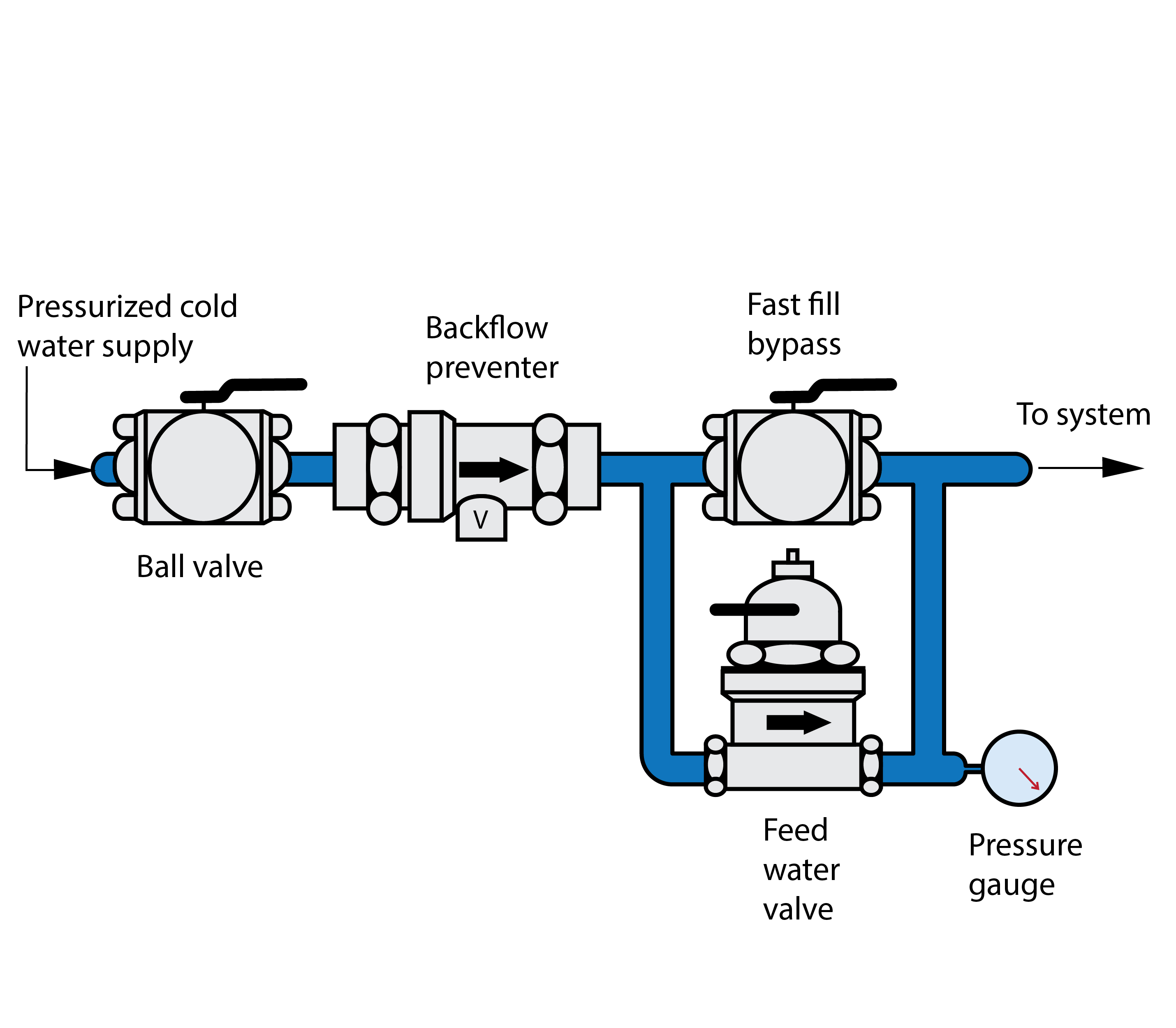
The flow speed through the feed water valve when in quick-fill mode is usually sufficient to purge a typical residential system. On larger systems, it is common practice to install a bypass valve (usually a full port ball valve) to provide even faster filling and purging flow (Figure 6). Notice the bypass ball valve is installed on the piping run to minimize the pressure drop for fastest possible purging. This bypass valve should be closed and marked, so it remains closed during normal system operation.
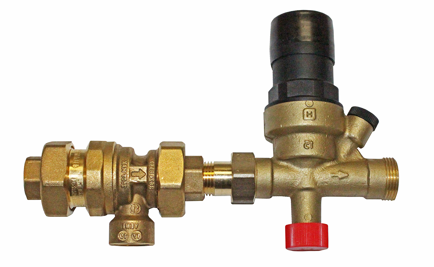
The backflow preventer is located on the feedwater line in series with the feedwater valve, and in some cases, they are available as a packaged unit (Figure 7). It is important to note that the backflow preventer is always installed upstream of the feedwater valve. This ensures that the pressure drop through the backflow preventer does not affect the final fill pressure setting provided by the feedwater valve. All quick-fill valves must be installed so as to not bypass the backflow preventer.
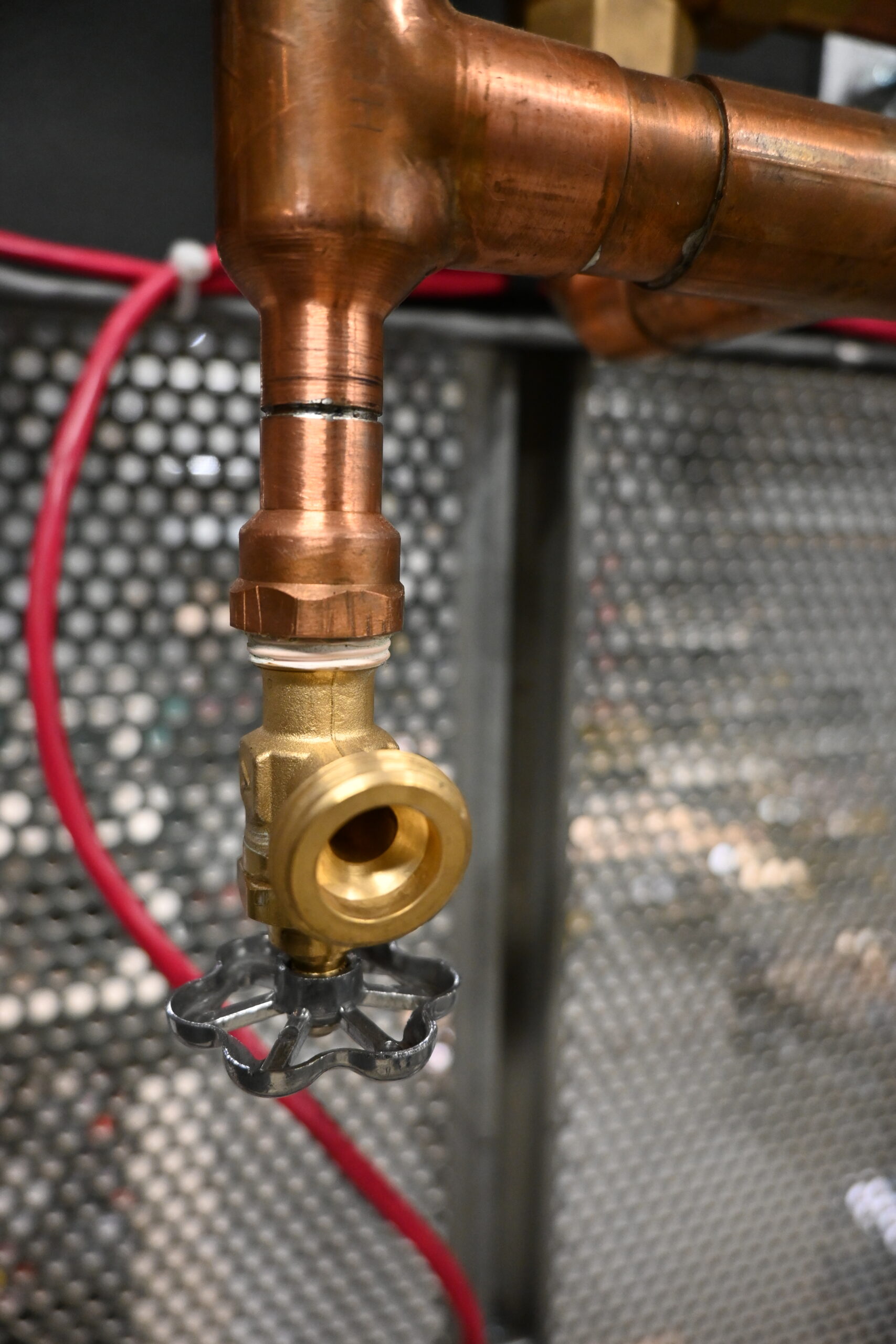
Purge Valves
During the initial filling of a hydronic system, most of the air that is in the empty system can be effectively pushed out of the system using the pressure and velocity of the water entering through the makeup line. This is sometimes called power purging or gravity purging, and it reduces the time needed to bleed the air through high-point vents.
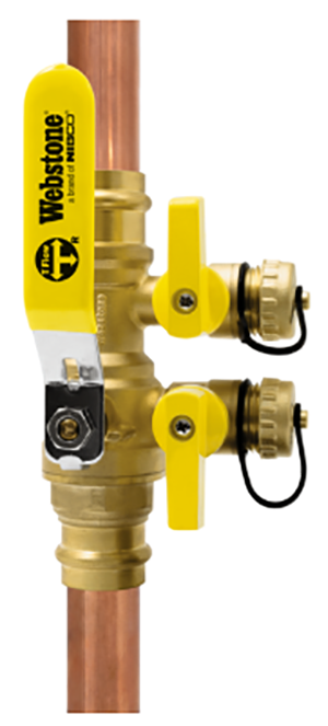
The purge valve is located on the return piping near the boiler. Modern purging valves consist of two ball valves in one common body. One ball valve is in line with the system, while the other is a side outlet port with a hs connection. Figure 8 shows two types of manufacture purge valve arrangements. Having different configuration options gives the installer location flexibility. The valve on the left has added installation versatility, as it has a three port ball with a reversible handle, which allows it to be set up for draining from either side of the ball.
Many wall-hung boilers come supplied with specialty purge valves kits for the supply and return connections (Figure 9).
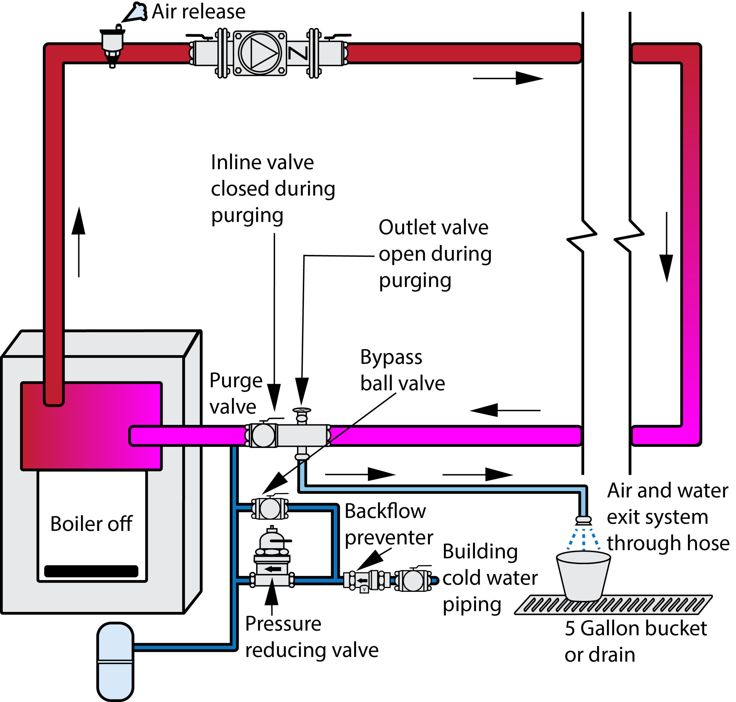
When purging the system (Figure 10), the inline ball valve is closed and the side outlet ball valve is opened, with a hose attached to it directing the water/air to a drain. The feedwater valve bypass or piped bypass can be fully opened to quickly let water into the system. As water enters the system, the air that previously filled the system is pushed out through the purge valve. Continue to fill the system until the fluid stream exiting the outlet port of the purge valve is free of visible bubbles. The bypass valve or quick-fill lever is then closed, the side outlet valve is closed, and the inline ball valve is opened. With the feedwater valve now set to work automatically, the system should require minimal manual bleeding of air. Pressures within the building piping feeding the quick-fill valve are almost always higher than the boiler relief valve; therefore, the boiler should be isolated, or this power purge will typically trip the relief valve. A cast-iron boiler should never be subjected to pressures over 30 psig.
For a newly constructed building, it is important that the water supply piping has been thoroughly flushed before using the auto fill as a purge supply. If there is any doubt as to the quality of the water supply, or if the potable supply has not been commissioned yet, it may be necessary to connect to an external source or purge cart. In this case, the previously described flushing procedure that used a three-valve arrangement would be used. For ease of installation, there are specialty manufactured double port flushing valve arrangements available (Figure 11).
Flow Check Valve
When water is heated, it becomes less dense than the cooler water on the return side of the boiler. During the off cycle of a boiler, hot water still has the tendency to rise up through the heating system and provide flow and heat, even when none is needed. This is referred to as thermal siphoning or gravity flow. Flow check valves are designed with a weighted internal plug (Figure 12) or a spring that is heavy enough to stop thermal siphoning or gravity flow of hot water while the system’s circulator is off, but light enough not to cause unwanted resistance for the pump. They also act like a basic check valve and will prevent reverse flow in a multizone system.
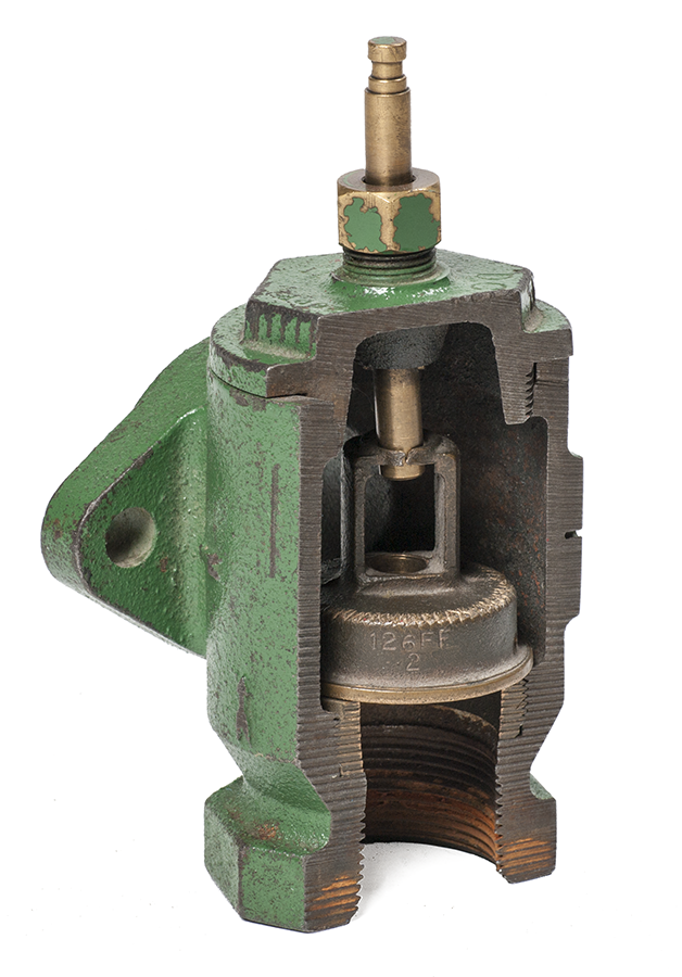
The stem at the top allows the valve to be manually opened if gravity circulation is desired or for draining the system.
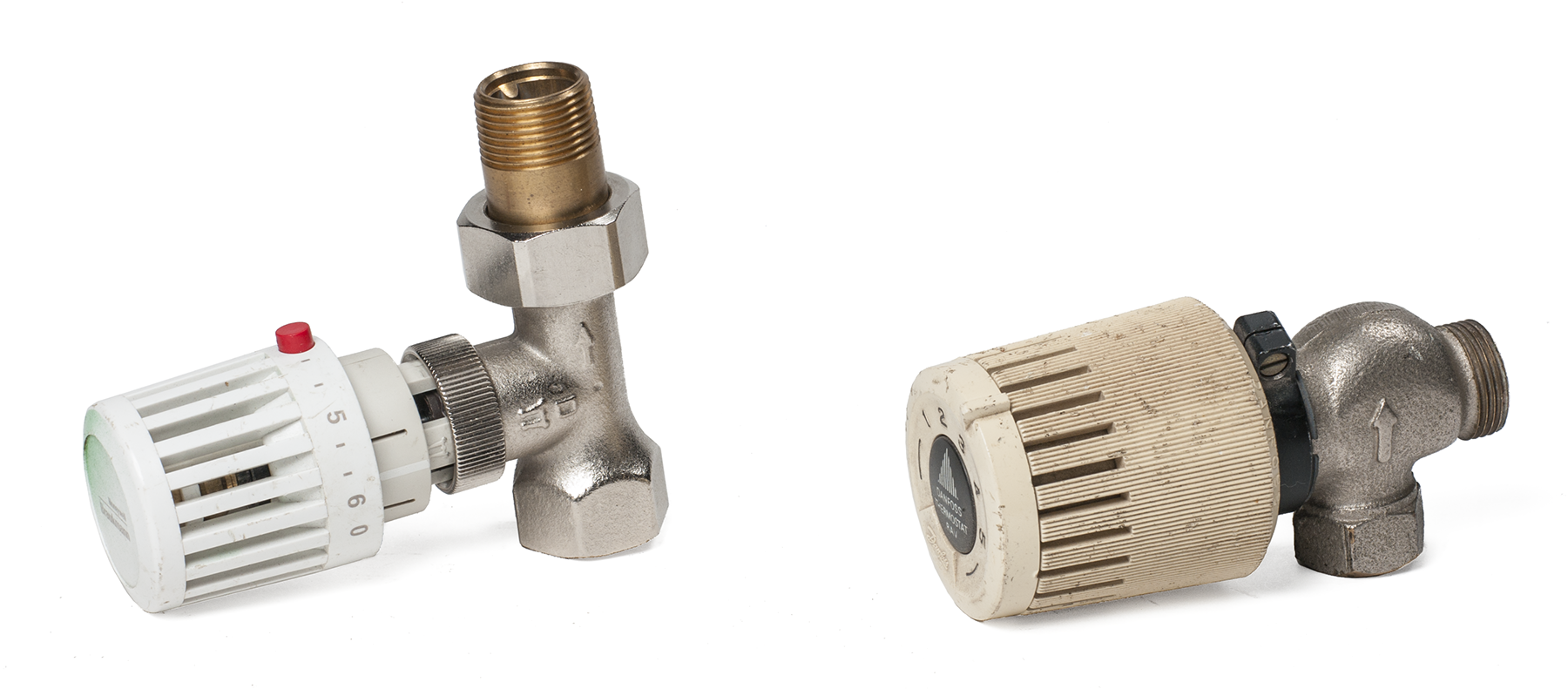
Thermostatic Radiator Valve
The thermostatic radiator valve (TRV) (Figure 13), is a device installed in the inlet or supply side of a heat transfer unit (HTU) and is normally used on a constant flow system. It contains two parts: the valve body and the thermostatic operator. The thermostatic operator senses the temperature of the room air surrounding the valve and forces the valve to either open or close. The TRV can also be fitted with a capillary tube and bulb mounted near the bottom of the HTU that senses the temperature of the air being pulled into the HTU through convection currents.
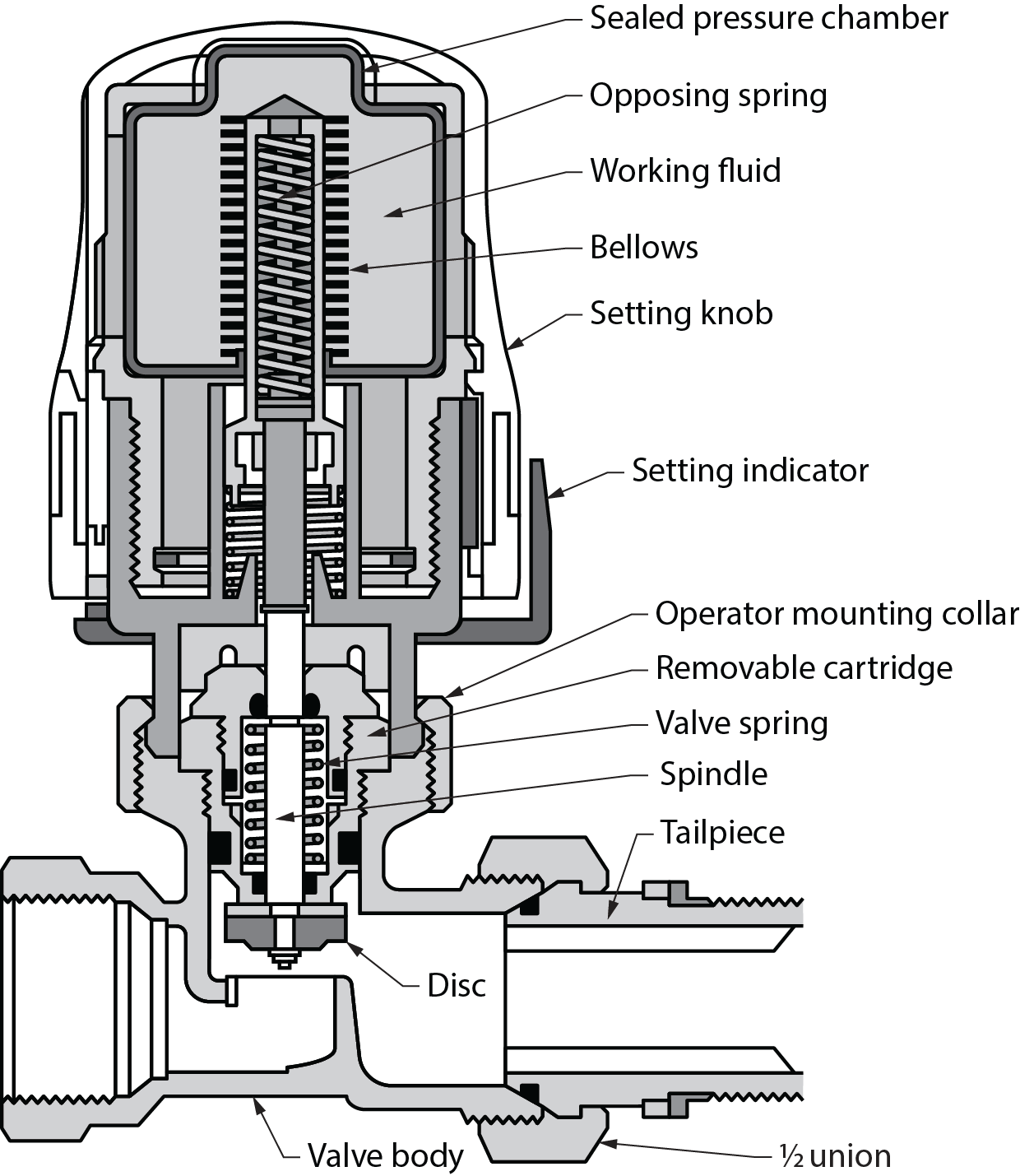
Opening the TRV allows more water to flow through the heat transfer unit, causing an increase in the room temperature; closing the TRV does the opposite. The opening and closing of the TRV is done using a spring, a bellows, and a fluid located inside the bellows (Figure 14).
The spring inside the TRV normally holds the valve open, allowing hot water to flow through the heat transfer unit; it will close to stop water flow when the room temperature rises to its set point. This is accomplished through the use of a fluid inside the bellows, which heats up and expands in reaction to the room temperature increasing. The force of the expansion causes the bellows to act upon the valve plug to overcome the opening force of the spring and eventually close the valve. In the reverse, as the room temperature drops, the liquid cools and contracts, releasing the pressure on the bellows and allowing the spring to push the valve open. This allows water to pass through the heat transfer unit, and the whole process starts again.
Thermostatic radiator valves can also be controlled via a wall-mounted thermostat. The thermostat senses room temperature and has a capillary tube connecting it to an operator mounted onto the valve on the heat transfer unit. The operation is similar to that of the directly mounted thermostatic valve except that the sensor is now remote to the valve itself. The advantage to this setup is that room temperature is controlled at thermostat height; the drawback is that the exposed capillary tube will be surface-mounted and must be covered to be aesthetically acceptable and also protect it from damage.
Zone Valves
One of the main benefits of a hydronic heating system is the ability to independently control different areas of the building or “zones.” Zone valves play a big part in this control strategy.
Zone valves permit or prevent the flow of water through the zone they control. When a room thermostat senses the need for heat, it signals the control valve for that zone to open.
There are two types of electrically operated zone valves:
- Motor operated actuator
- Wax filled actuator
Their difference is relative to their operation.
Motor Operated Zone Valves
Motorized zone valves are operated by electric motors activated by a 24-volt signal from the thermostat in that zone. Figure 15 shows a [latex]\tfrac{3}{4}[/latex]-inch motorized zone valve with sweat connections intended for installation on copper tubing.
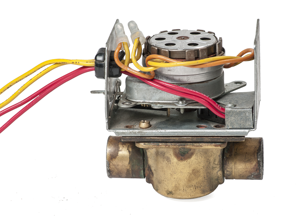
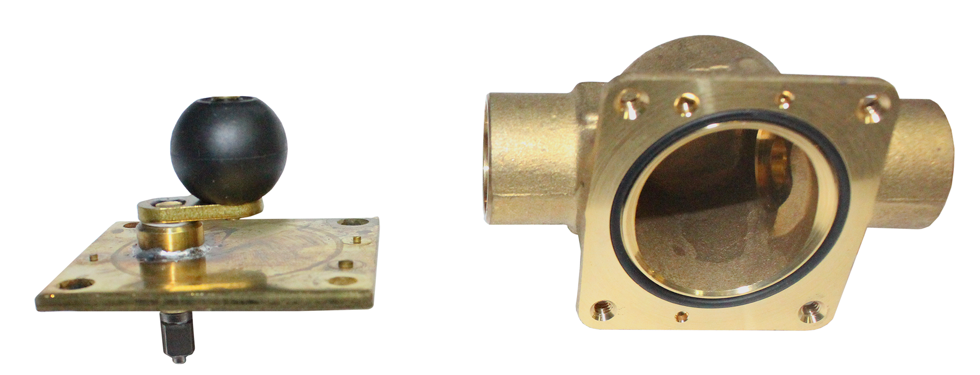
The electrically controlled motor drives an actuator with a rubber ball mounted on it (Figure 16). When a call for heat occurs, 24 volts AC is sent to the zone valve motor through the yellow wires. The motor spins to move the actuator, and the rubber ball moves away from the opening connected to the piping. Water pushed by a circulator is then able to flow through the piping in that zone. When the call for heat is satisfied, the thermostat contacts open and power to the zone valve is interrupted. A spring then pulls the actuator back to its original position, and the valve closes.
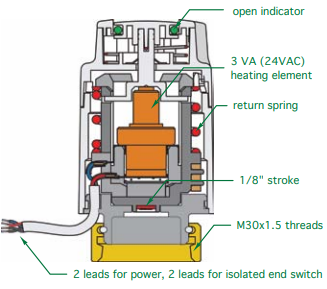
Wax Filled Actuators
Zone valves controlled by a wax filled actuator use a similar valve design as the one shown for thermostatic radiator valves. These valves are opened and closed with a simple linear (versus rotational) movement of their shaft. When the unenergized actuator (Figure 17) is mounted onto the valve body, the cool contracted wax and an internal spring push down onto the valve stem and close the valve. On a call for heat, the valve is energized with 24 VAC and a small heating element warms the wax chamber; the expanding wax lifts up a piston assembly and opens the valve.
The total movement of the actuator shaft is only about [latex]\tfrac{1}{8}[/latex] of an inch. The movement of the shaft is slow. A typical actuator reaches its fully open position two to three minutes after power is first applied, which is preferred on a radiant system to avoid unnecessary opening for a brief room draft that will be picked up by the high mass of the system.
Zone valves are normally installed on the supply side of each zone circuit. This is done so that heat migration will not occur during the off cycle. If the zone valve is installed on the return from a circuit, the supply to that circuit should have a flow check installed.
Zone valves are available in two-wire and four-wire configurations. In a two-wire configuration, power is only sent to the actuator to open and close the valve. A four-wire configuration is used when a circulating pump is required to turn it on but only if a zone valve is open. In this case, there needs to be some way for the system to recognize that there is somewhere for the water to go. The four-wire configuration has two extra wires that incorporate an end switch to prove that the valve is open.
The end switch is simply a proving switch. As the zone valve actuator arm moves, a small metal plate attached to the arm moves with it. Only when the zone valve is fully open does this metal plate press against a microswitch, closing it and allowing the electricity to travel through the switch’s red wires to the pump relay. The relay coil energizes, which closes internal contacts and turns the pump on.
If the zone valve fails to open, the end switch will not close, and the pump will not start. This saves the pump from “deadheading” (spinning the impellor without letting water flow), which will eventually cause the pump to fail.
System Operating Pressure Controls
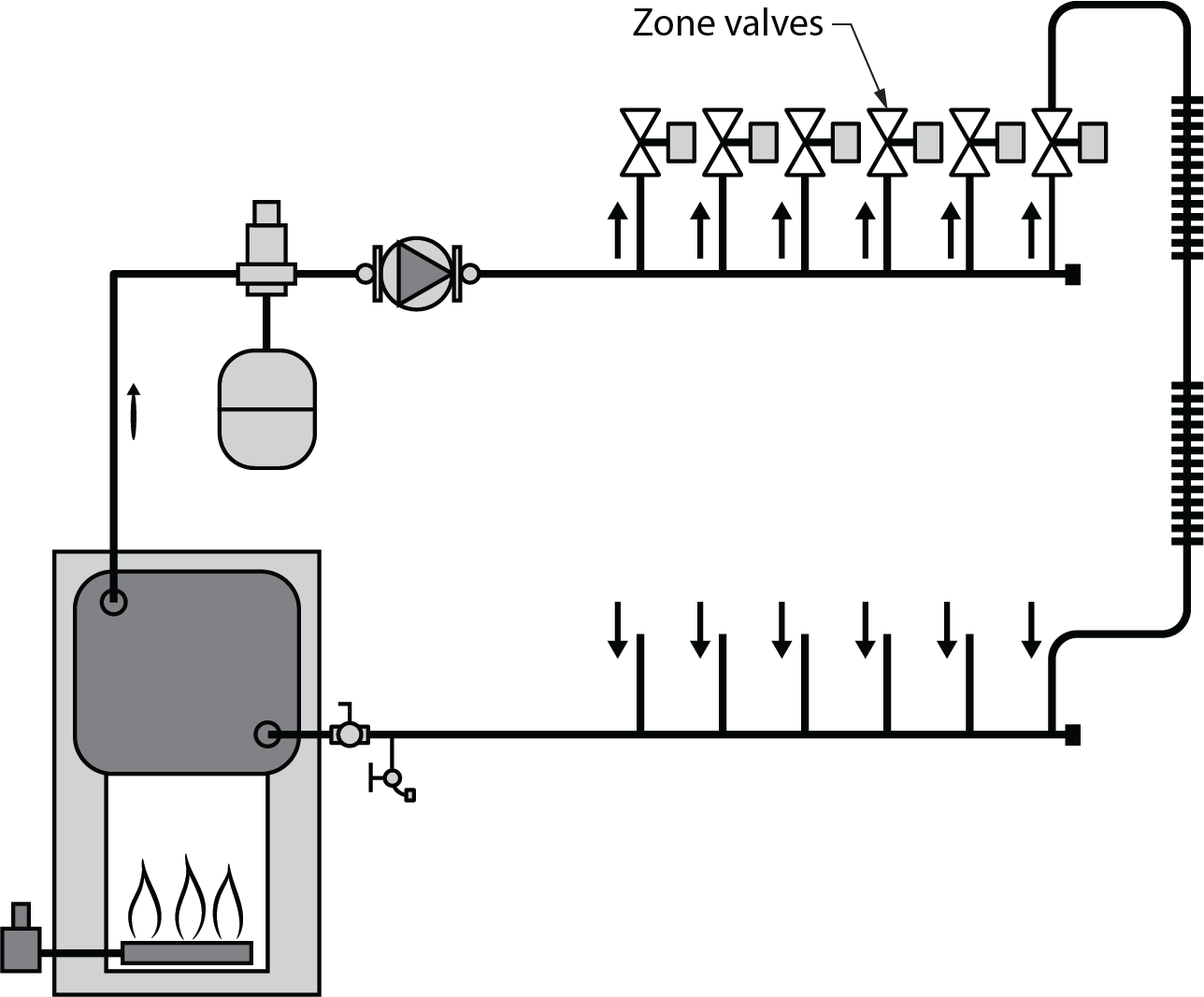
Figure 18 shows a number of zones being supplied by one fixed-speed circulator. As zone valves are closed, the flow resistance of the system is increased and the zones that remain open “feel” this increased differential pressure, and their flow rates immediately increase. In some systems, the increased pressure differential and flow velocity may be of little consequence. In others, it may be sufficient to create flow noise, pipe erosion, and valve stem lift.
Reducing excess system pressure created by zoning can be achieved by two common methods:
- Differential bypass valve
- Pressure-regulated circulator
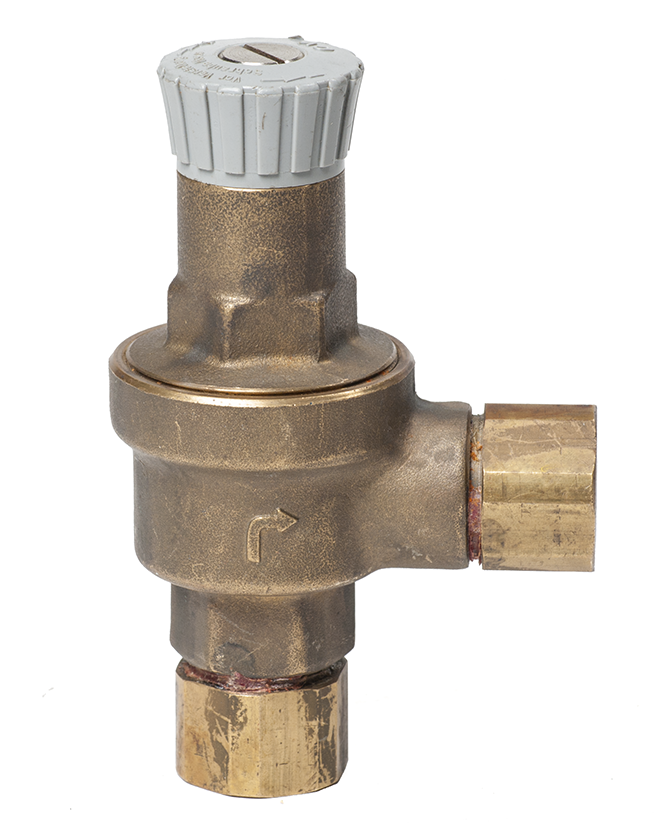
A differential bypass valve (Figure 19) is like an adjustable spring-loaded pressure relief valve. The setting knob adjusts the force exerted by the compression spring on the valve.
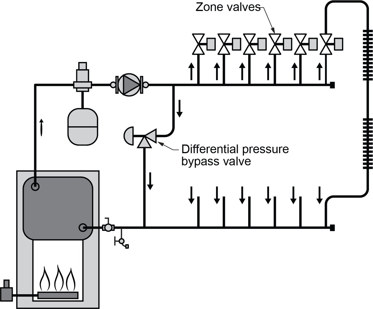
Essentially, it gives the pump another route to pump through if most or all zone valves are closed (Figure 20).
The spring pressure should be set so there is just enough tension to keep it in the closed position when the system is balanced with all zones are open. As zone valves close and the differential pressure across the headers increases, the differential bypass valve should begin opening when the differential pressure reaches 0.5 to 1 psi above the differential pressure present when all zone circuits are open. The result is a minimal change in the differential pressure between the supply and return headers.
The disadvantage of using a bypass valve is that, at times, when zone valves are closed, the pump is wasting some of its energy. As described in the Section B-4.1, another way of regulating excess pressure in hydronic systems is through the use of variable speed circulators. These pressure-regulated ECM circulators are ideal for systems using valve-based zoning and eliminate the need for a differential pressure bypass valve.
When a valve in a branch circuit closes or modulates to reduce flow, the circulator detects an increase in differential pressure across it. It quickly responds by lowering its speed to counteract this change in differential pressure. As additional valves in other branch circuits close or modulate to reduce flow, the circulator continues to adjust its speed accordingly to maintain the set differential pressure. This process, known as “constant differential pressure control,” mode, conserves electrical energy that would otherwise be wasted by operating at a fixed speed.
Balancing Valves
Hydronic systems containing two or more parallel piping paths often require adjustments of the flow rates to ensure even heat distribution. This is especially true in two-pipe direct-return systems where, without balancing valves, these systems would produce higher flow rates in the piping paths closest to the circulator compared to those farther out in the distribution system. The proper use of balancing valves can correct for this situation.
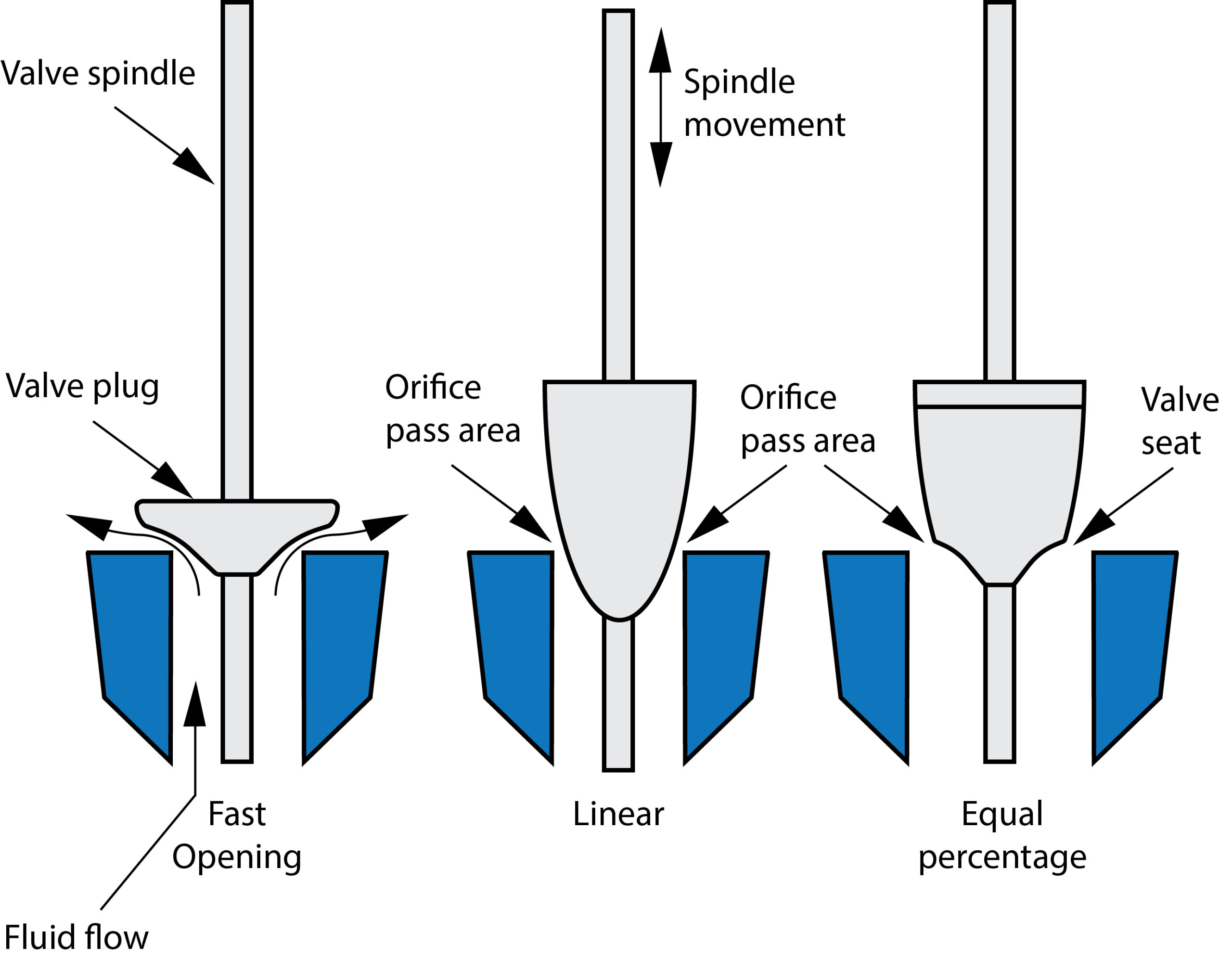
Most balancing valves are a type of globe valve that has much less flow restriction through it. A globe valve with a convention disc or plug (Figure 21, left) has a quick opening characteristic which makes them much more difficult to use for the precise flow balancing required on hydronic heating systems. On the linear and equal percentage globe style valves (Figure 21, centre and right), the disc is more cone-shaped, making more of it protrude into the seat. This allows more precise setting of the flow control plug and thus, provides better control of flow rate.
Selecting Balancing Valves
A balancing valve operates best at between 50% and 100% of the maximum opening. Select the balancing valve so that the required pressure drop will be within this range. Do not use a balancing valve that is larger than necessary. Not only does a larger valve cost more, but it will also operate near the closed position, which may give poor flow accuracy. The balancing valve should never be larger than the size of the pipe.
Manufacturers’ specifications indicate the flow capacity and pressure drop limits of balancing valves.
There are a variety of balancing valves available to suit the needs of the different systems, some of these include:
- Lockshield valves
- Flow metering balancing valves
- Differential pressure balancing valves
- Automatic flow balancing valves
Lockshield Valves
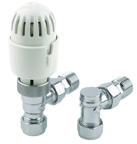
Lockshield balancing valves are most commonly used to balance the flow on radiators. They are often paired with a thermostatic rad valve (Figure 22). To adjust the flow setting of a lockshield valve, the cap is removed, and the internal plug is rotated with an Allen key. The valves come complete with a half union, which allows the valve to be easily separated in position from the radiator.
Flow Meter Balancing Valves
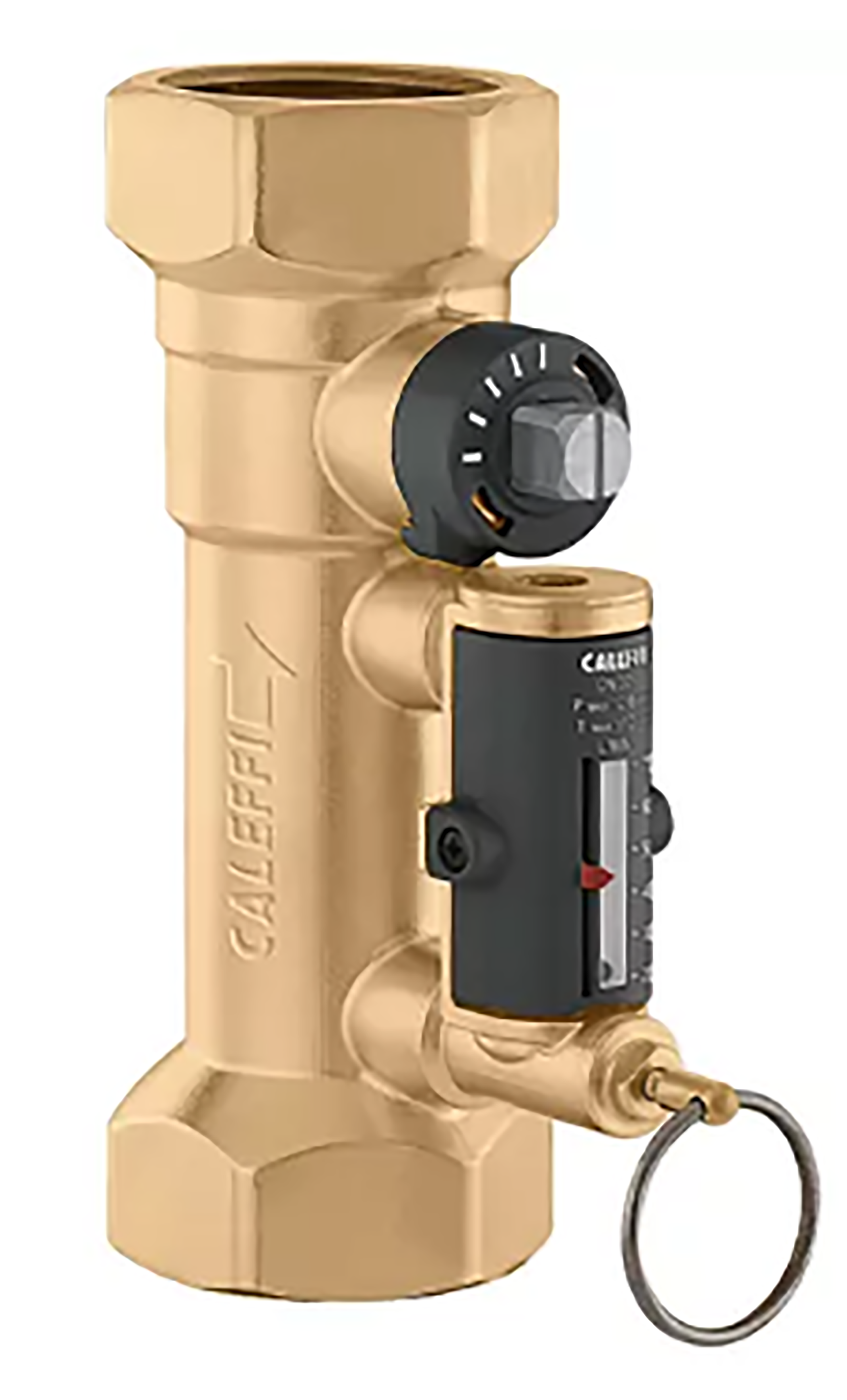
Some balancing valves have a self-contained flow meter. On some valves, the flow can be read continuously; on others (Figure 23), the reading is taken by pulling an actuating pin.
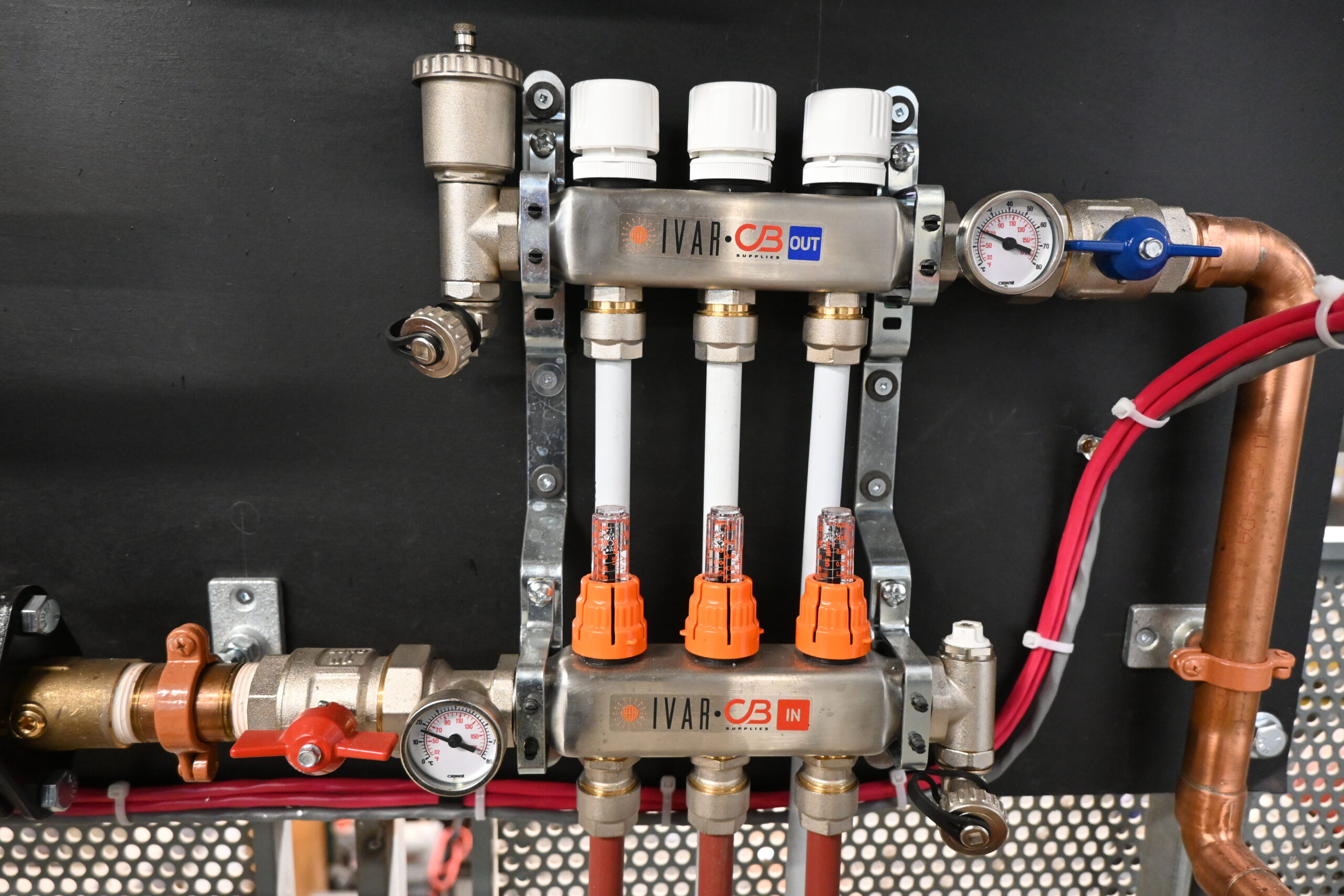
Most manifolds for radiant in floor systems will have self-contained flow meter balancing valves for each radiant loop (Figure 24). For some types, the flow adjustments to each circuit are made by rotating the flow indicator column, which is directly connected to the shaft of the internal valve. For others, the flow adjustment may be located underneath the electric zone operator to hinder owners making their own adjustment after the system has been balanced.
Differential Pressure Balancing Valves
Differential pressure type balancing valves work on a known relationship between flow rate and the pressure drop across the valve. The valves have two ports, one on each side of the disk/seat (Figure 25), that allow connection of a differential pressure measuring device. The flow rate through the valve can then be found using a chart, slide rule, or electronic device.
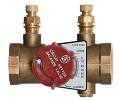
The ports are sometimes called Pete’s plugs. This is a twist on the term PT plugs to indicate plugs or ports that can be used to measure pressure and/ or temperature.
Another variation of a differential pressure balancing valve locates the pressure ports on either side of an internal venturi (Figure 26). The venturi passage maintains a more stable relationship between differential pressure and flow rate than that of valves that measure differential pressure across the flow plug.
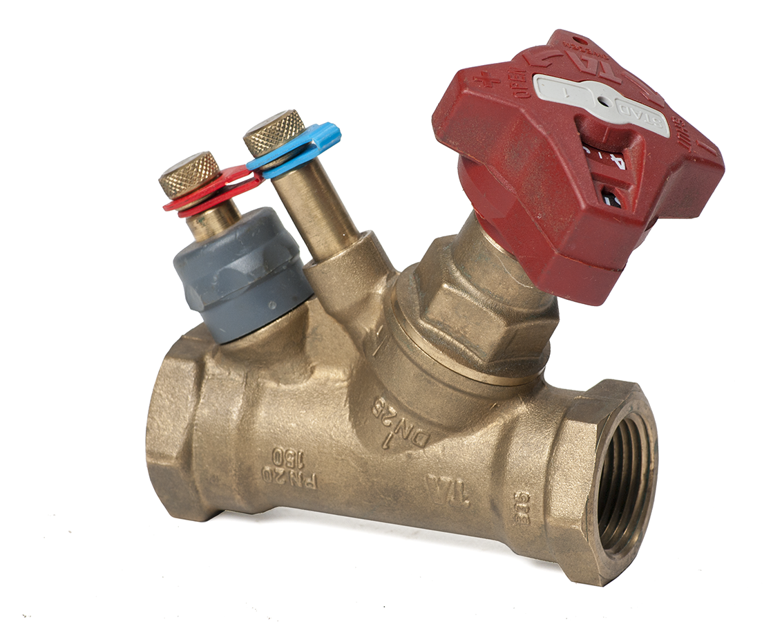
For both types of these types of differential pressure balancing valves, the adjusting knob has setting numbers or increments that must be used to select the proper flow scale on the manufacturer’s chart.
Automatic Flow Balancing Valves
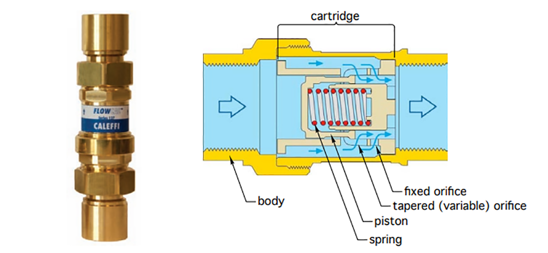
Automatic flow balancing valves use an internal cartridge that maintains a specific flow rate over a wide range of system differential pressure ranges. The cartridge consists of a cylinder, a spring-loaded piston, and a combination of fixed- and variable-shaped orifices through which flow passes (Figure 27). The piston automatically adjusts its position based on the amount of thrust created by the differential pressure across the valve. Different cartridges are available for different flow rate requirements.
Mixing Valves (Tempering Valves)
Some hydronic distribution systems require water temperatures that are substantially lower than the temperatures supplied by the heat source. For example, a radiant floor heating system may require water at 43°C (110°F), while the water temperature from the non-condensing boiler may be over 82°C (180°F). In such cases, the lower water temperature is created by blending water returning from the distribution system with hot water from the heat source. The flow rate of each stream can be regulated by a mixing valve to attain the desired supply temperature.
There are several types of valves used in hydronic heating systems to achieve the water temperatures needed. They include valves operated by electrically motorized actuators, as well as by thermostatic sensors and actuators. The sections that follow describe several types of mixing valves and briefly illustrate how they are used. As well, it is important to note that the term “mixing valve” is used generically in the industry to mean any valve that blends two temperatures of water to achieve a lower temperature. The following section breaks that generic terminology down into more definite terms.
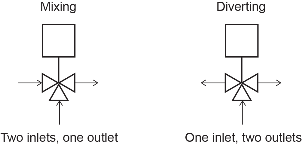
Diverting Valve
A diverting valve (Figure 28) is not actually a mixing valve but is simply a valve designed to divert flow. It has one inlet port and two outlet ports and is not designed to mix any fluids within its body.
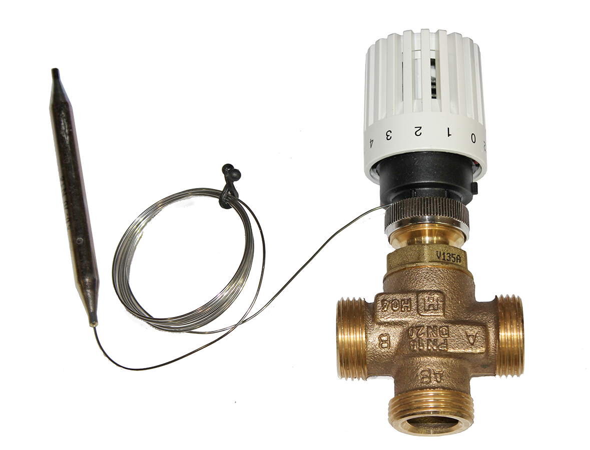
Figure 29 shows the difference between using a three way valve as a mixing valve or a diverting valve.
A diverting valve is located on the return side of the system, similar to a mixing valve (Figure 30). The flow coming into the valve is the return water from the system. Typically, a three-way diverting valve will divide the cooler system’s return water into two flows. A portion of the flow (approximately 25%) goes to the boiler to be reheated. The rest (approximately 75%) bypasses the boiler to meet and mix with the heated water from the boiler in the system piping. These ratios can vary widely depending on the water temperature required for the heating application.
Diverting valves can be either manually or automatically controlled. If automatic control is desired, the valve must have a remote sensor bulb with a capillary tube mounted downstream of the system mixing point and connected to the valve. A diverting valve achieves finer control and has less head loss through it than a mixing valve.
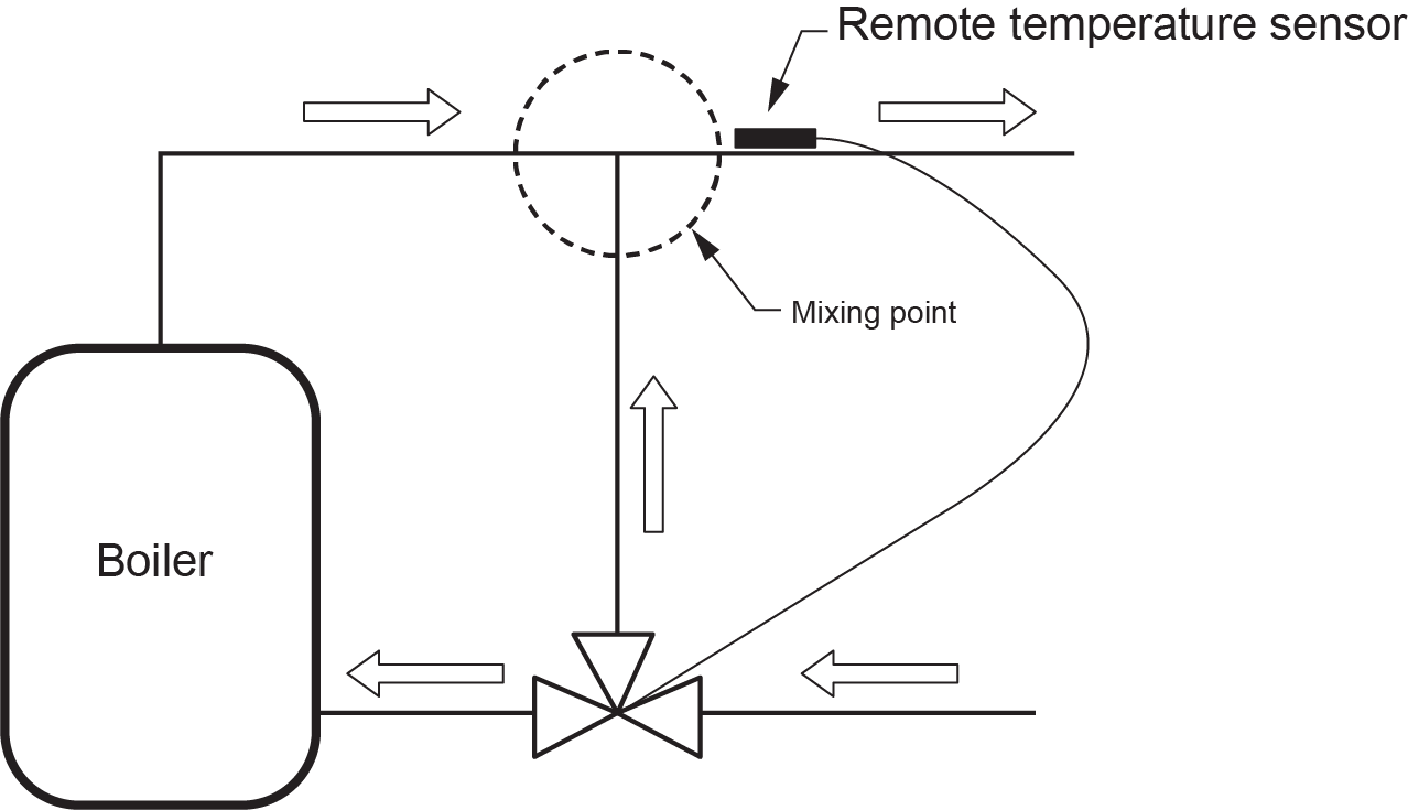
The mixture of hot boiler water and cool system return water is necessary to maintain the desired temperature needed in a radiant floor system and protect the boiler against lower-than-allowed return water temperatures.
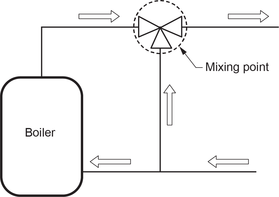
Three-Way Mixing Valve
Like the three-way diverting valve, a three-way mixing valve is also a three-port valve, but it has two inlet ports (one for hot water and the other for cool water) and one outlet port, which is tempered water. Also, unlike the three-way diverting valve, the mixing of the two fluids with the three-way mixing valve occurs inside the valve body itself (Figure 31).
The positioning of the internal valve mechanism determines how much of each fluid will enter the valve body. Adjusting the knob on the valve adjusts the water from each of the hot and cool ports.
A three-way mixing valve can come with or without an actuator. Without an actuator, it cannot adjust itself to compensate for changes in the temperature of incoming water. If automatic water temperature control is required, the addition of an actuator allows the valve to adjust the outgoing water temperature automatically.
If a boiler is unable to handle lower water return temperature, which may result in condensation, then a three-way mixing valve may not be the best option. In that case, a four-way mixing valve might be a better option.
Four-Way Mixing Valve
The basic difference between three-way and four-way mixing valves is that four-way mixing valves (Figure 32) can control the water temperature and flow rates to both the supply piping and return piping to the boiler.
Cool return water is mixed with the hot supply water to achieve the desired temperature to supply the system. The valve also mixes hot supply water and cool return water to maintain boiler return water temperatures above 60° (140°F). This ensures that the water entering the boiler is hot enough to avoid any possible condensation issues.
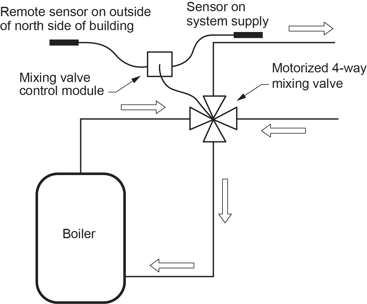
Like the three-way mixing valve, a four-way mixing valve can be used either with or without an actuator to provide better mixed water temperature control. Motorized actuators for four-way valves often incorporate outdoor sensors to automatically raise or lower the system water temperature in response to changes in outdoor temperature. This control strategy is called outdoor reset.
Figure 33 shows different internal water pathways and mixing created with different valve positioning.
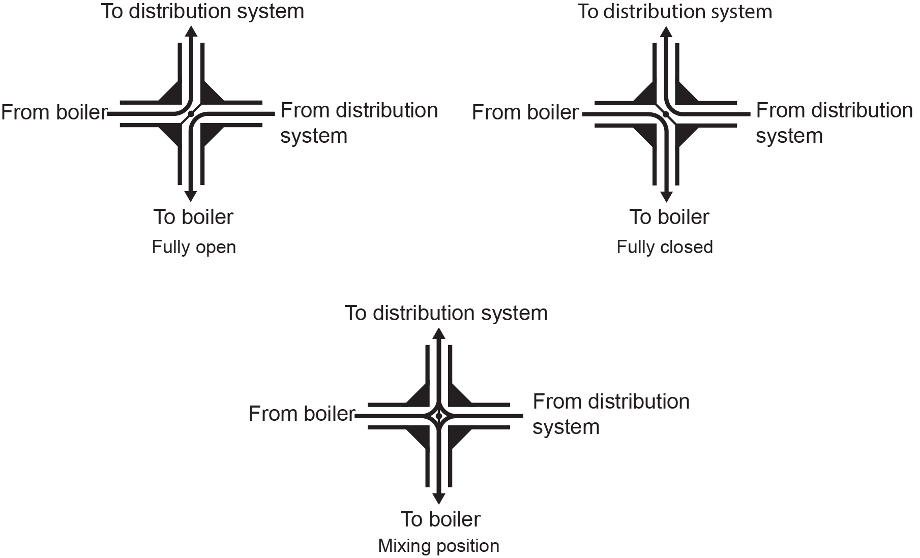
Figure 34 shows the piping required for a four-way mixing valve configuration.
 Self-Test B-4.2: Hydronic System Valves
Complete the chapter Self-Test B-4.2 and check your answers.
If you are using a printed copy, please find Self-Test B-4.2 and Answer Key at the end of this section. If you prefer, you can scan the QR code with your digital device to go directly to the interactive Self-Test.

References
(2018, April 4). Control valve characteristics [digital image]. automationforum.co. Retrieved from https://automationforum.co/control-valve-characteristics/
Caleffi Hydronic Solutions. (2009, July). Figure 3-15, a 4-wire valve actuator, Zoning hydronic systems [digital image]. idronicsTM (5), 2009, 16. https://idronics.caleffi.com/magazine/15-separation-hydronic-systems
Caleffi Hydronic Solutions. (2010, July). Figure 3-15, direct-reading balancing valve, Hydronic balancing [digital image]. idronicsTM (8), 2010, 21. https://idronics.caleffi.com/magazine/8-hydronic-balancing
Caleffi Hydronic Solutions. (n.d.). Balancing valve with flow meter [product image]. https://www.caleffi.com/en-int/balancing-valve-with-flow-meter-132-caleffi-132402
HPAC Magazine. (2017, December 18). Figure 3: Purging hydronic circuits [digital image]. In Siegenthaler, J. (author), “Hydronic circuit purging: The basics.” Retrieved from https://www.hpacmag.com/features/purging-hydronic-circuits/attachment/hpac-dec-2017-fig-3/
Nibco Inc. (n.d.). E-X-P® Tankless Water Heater Service Valves. Retrieved from https://www.nibco.com/brands/webstone/e-x-p-series/e-x-p-TWH/
Nibco Inc. (n.d.). Pro-pal purge & fill [digital product image]. Retrieved from https://www.nibco.com/nibco-products/valves/ball-valves-combination/h-x861/
MHS Radiators (n.d.). Sterling TRV [digital product image of radiator]. https://www.mhsradiators.co.uk/product-item/sterling/
Skilled Trades BC. (2021). Book 1: Fuel gas systems, Heating and cooling Systems. Plumber apprenticeship program level 2 book 1 Harmonized. Crown Publications: King’s Printer for British Columbia.
Trades Training BC. (2021). B-4: Install hydronic heating piping and components. In: Plumber Apprenticeship Program: Level 2. Industry Training Authority, BC.
Xylem. (n.d.). Bell & Gossett circuit setter plus calibrated balance valves [digital product image]. Xylem US. https://www.xylem.com/en-us/brands/bell-gossett/bell–gossett-products/all-bell-gossett-products/circuit-setter-plus-calibrated-balance-valves/drawings/
Media Attributions
All figures are used with permission from Skilled Trades BC (2021), licensed under a CC BY-NC-SA license, unless otherwise noted.
- Figure 6 Quick fill bypass arrangement by TRU Open Press. CC BY-NC-SA
- Figure 8 Purge valve/drain valve is by TRU Open Press. CC BY NC SA
- Figure 9 Wall hung boiler service valves is by Nibco Inc. (n.d.) and is used with permission.
- Figure 10 Purging air from system was modified by TRU Open Press, from original image in HPAC Magazine (2017).
- Figure 11 Double port purge valve is by Nibco Inc. (n.d.) and is used with permission.
- Figure 17 Wax filled zone valve actuator [Fig 3-15] is by Caleffi Hydronic Solutions (2009) and is used with permission.
- Figure 21 Valve plug shapes modified by TRU Open Press from original image by in Automationforum.co (2018) – used under Fair Dealing.
- Figure 22 Sterling TRV radiator valves is from MHS Radiators (n.d.) and is used with permission.
- Figure 23 Caleffi QuicksetterTM balancing valve is from Caleffi Hydronic Solutions (2010) and is used with permission.
- Figure 25 Bell & Gossett circuit setter balance valve is from Xylem (n.d.) and is used with permission.
These valves protect the boiler against a runaway fire. On space-heating steam boilers, the relief valve is set to pop open and relieve pressure at 15 psi. This is the limit for any low-pressure boiler. (Section B-1.2, Section B-4.1, and Section B-4.2)
A valve that controls the flow of liquid using a ball with a hole through the center. When the ball is turned so that the hole lines up with the pipe, liquid flows through. When the ball is turned so that the hole is perpendicular to the pipe, the flow is blocked. Ball valves are known for their quick and easy on-off operation. (Section B-4.2)
A device that stops water from flowing backward into the water supply. It ensures that water doesn't get contaminated by preventing dirty or used water from flowing back into clean water lines. (Section B-4.2)
A valve that controls the amount of water that enters a system and lowers the pressure to a safe level. It helps keep the water pressure steady and safe for the system. (Section B-4.2)
Radiator valves control the steam supply to the system radiators. Each radiator is equipped with an angle pattern radiator supply valve. (Section B-1.2 and Section 4.2)
