B-4.1 Hydronic Distribution System Components
This chapter will look at some common components found in a hydronic distribution system.
Circulating Pumps
The circulating pump’s job is to pump liquid through the piping system, from the heat source to the heat emitter and back to the source again. Because a hydronic heating system is a closed system, “circulator” is a more accurate description for this device.
The circulator must provide enough flow to meet the heat demands of the system while overcoming the head losses (pressure losses) of the system components. An undersized pump will not move enough water to provide enough heat transfer; an oversized pump will be noisy and cause excessive system pressure, increased water velocities, and higher energy consumption.
Types of Circulators
A hot-water heating system circulator will most likely be a centrifugal pump, which consists of an electric motor spinning an impeller within a housing (volute) containing liquid (Figure 1).
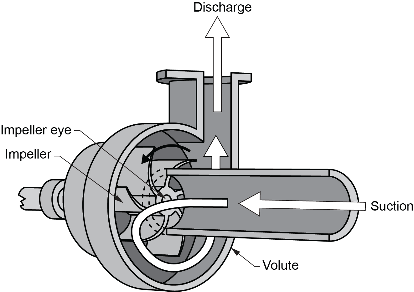
The water enters the circulator’s body through the inlet opening, which is very near the centre or “eye” of the impeller. This will be the point of lowest pressure in the entire piping system. As the impeller spins, centrifugal force throws the water from the impeller eye out along the blades (vanes) of the impeller to the impeller tips, which will be the point of highest pressure in the system. There is now an imbalance in pressures between the eye and the tips of the vanes of the impeller, and the only way for these pressures to equalize is for the water at the impeller tips to circulate through the system piping, eventually returning to the eye of the impeller.
Pressurized water from the impeller flows between the tips and the widening cavity inside the circulator’s casing, known as the volute, until it exits through the discharge port. The construction of the impeller dictates the pressure and volume of water created: the wider the impeller, the higher the volume of water it can move. The longer the vanes and the greater their number, the more pressure the impeller can create. Note that two seemingly identical circulators can have vastly different pressure and volume outputs. Always consult the manufacturers’ literature before selecting a circulator.
Wet-Rotor and Three-Piece Circulators
Circulator motors may be water-cooled or air-cooled. Water-cooled circulators are referred to as wet-rotor circulators. Older style conventional circulators are air-cooled; they are also referred to as three-piece circulators or dry-rotor pumps.
Wet-Rotor Circulators
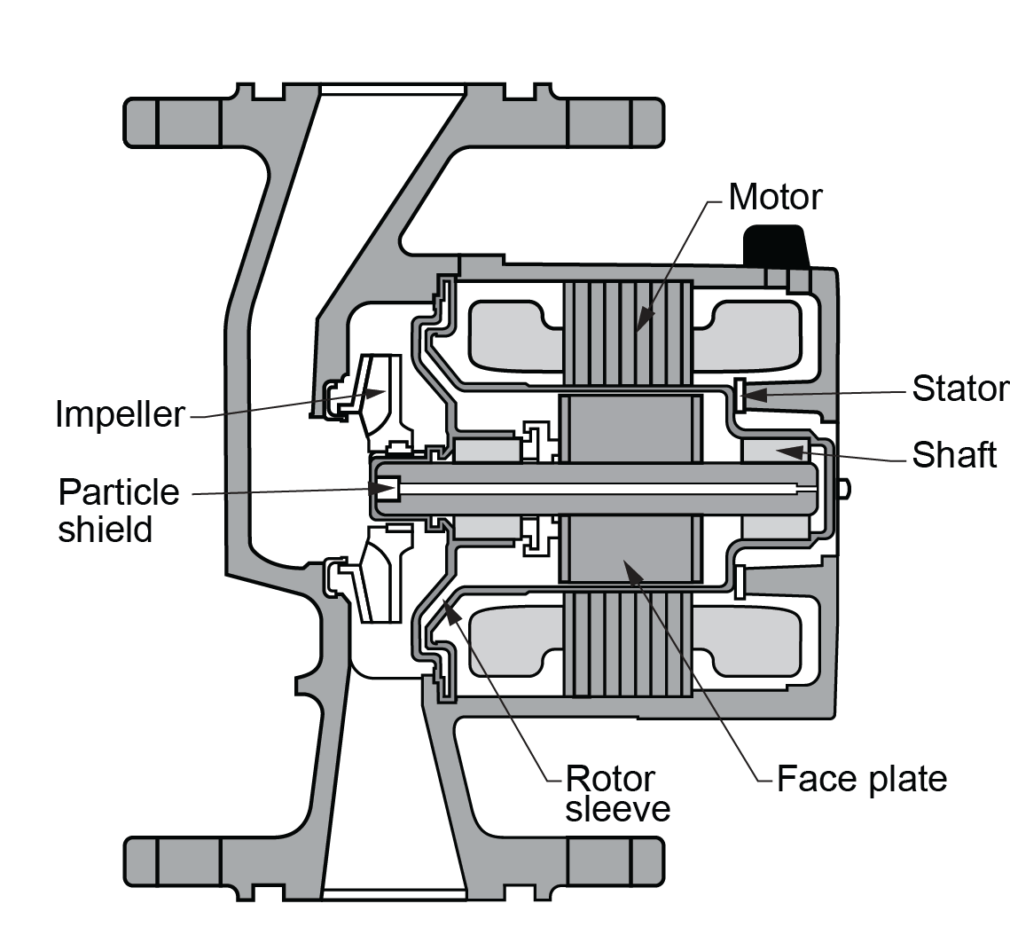
The wet-rotor circulator shown in Figure 2 has a water-cooled motor and water-lubricated bearing. These pump motors must be installed in the horizontal position, regardless of the orientation of the pump body, to ensure that the bearings will always be in contact with the system water. This is how the bearings are kept cool. Some models have a plug at the end of the motor shaft to vent air prior to pump startup.
Dry Rotor Circulators
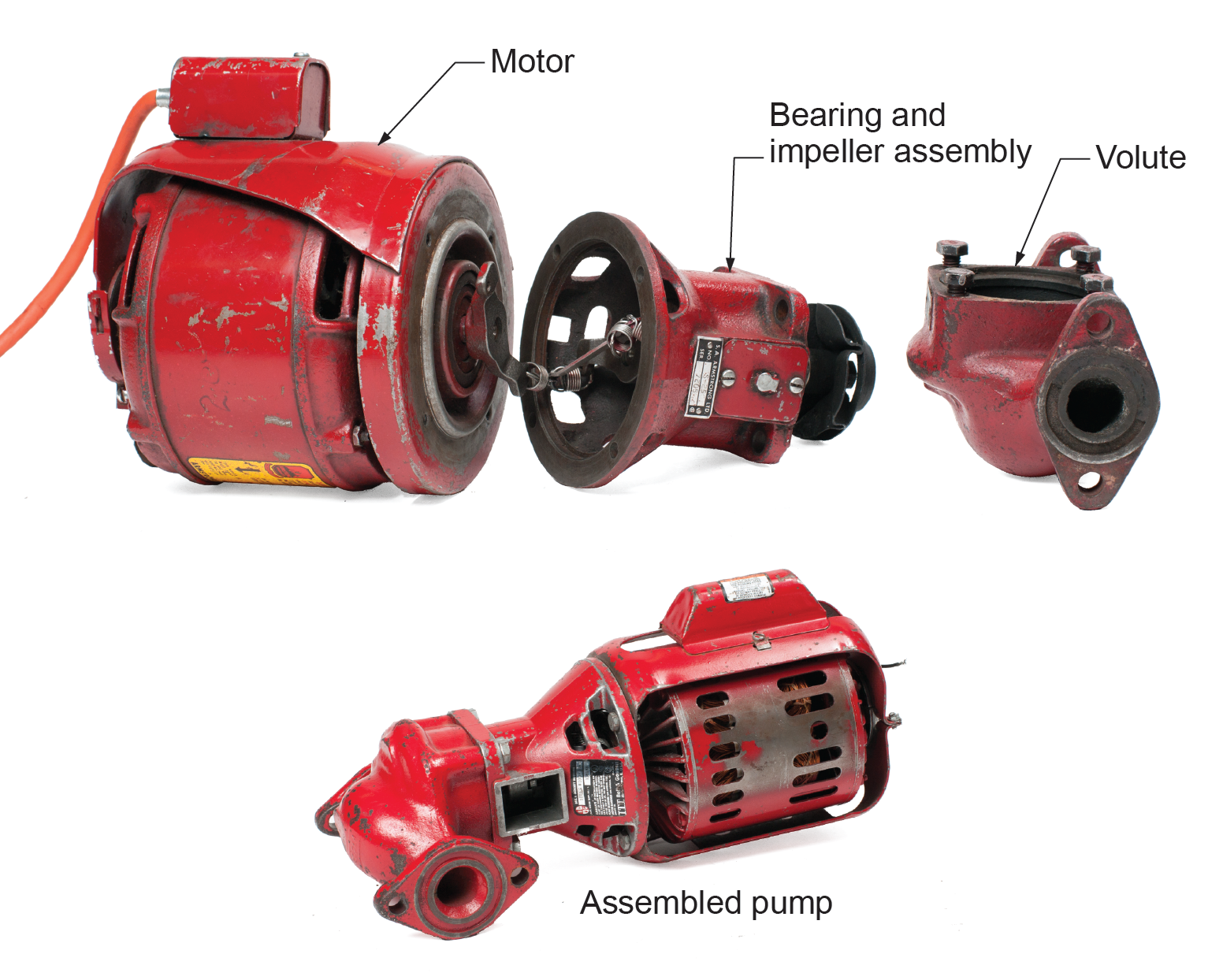
Dry rotor, or three-piece circulators (Figure 3), consist of a motor assembly, pump assembly, and coupling assembly. The motor is air-cooled, while the bearings are oil-lubricated. There are usually three oil filler receptacles for the motor and shaft bearings that must be oriented vertically and faced upward for initial filling and periodic oiling. Facing the oil filler receptacles in a downward position will prevent lubrication and allow any manufacturer’s oil to drain out of the bearing assembly, resulting in damage to the bearing. Like the wet-rotor circulators, the three-piece variety requires the shaft to be horizontal unless it is of the vertical shaft design. Dry-rotor pumps must have their bearings oiled upon installation and at regular intervals, as prescribed by the manufacturer.
Pump Location
Circulating pumps can be installed anywhere in the piping system because the systems are closed and balanced, but the preferred location is on the supply main immediately downstream of the compression tank.
The pump moves water by developing a difference in pressure between its inlet and outlet. This pressure differential can be either a help or a hindrance to the system. It is extremely important to understand the concept of the “point of no pressure change” (the location where the compression tank or its piping is connected to the system piping) and how the placement of the pump in relation to that point can make an important difference in system operation.
The “point of no pressure change” concept was discovered decades ago by an engineer working for Bell & Gossett, a well-known manufacturer of hydronics and a pioneer of the industry. The concept is simple: to change the set pressure in a piping system with an expansion or cushion tank connected to it, water would have to be added to or drained from the system. Whatever the pressure is in the air side of the expansion tank is what the pressure will be at the point of no pressure change on the “water side” of the expansion tank. Where the pump is placed can affect system operation, in particular, air control.
A pump does what it does because it creates a pressure differential between its inlet and its outlet. If the pump is installed immediately downstream of the point of no pressure change, it must add its developed pressure to the system’s static fill pressure to create flow.
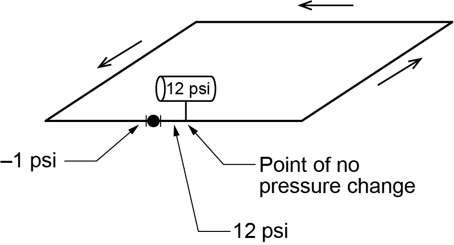
For example, if the pump can develop a 13 psi (91 kPa) pressure differential between its inlet and outlet where the static fill pressure is 12 psi (84 kPa), then the pressure at the pump’s outlet in this position will be 25 psi (175 kPa) (Figure 4).
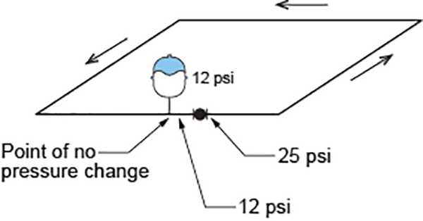
This extra pressure will help keep air entrained in the water, which helps prevent circulation problems caused by air coming out of the water and pocketing. Water cannot move if air is present.
If the pump is installed immediately upstream of the point of no pressure change, the pump cannot add to the system’s static fill pressure. To develop a difference in pressure between the pump’s inlet and outlet, the pump must drop its inlet pressure. For example, if the pump can develop 13 psi (91 kPa) and the static fill pressure is 12 psi (84 kPa), then the pressure at the pump inlet will be –1 psi (–7 kPa) (Figure 5). This pressure is below atmospheric pressure, so air will be pulled into the system wherever possible, such as through the automatic air vents, the stem packing on the valves near the pump, or the pump’s mechanical seal. This also contributes to pump cavitation. Cavitation is a phenomenon where air bubbles are pulled out of water through high temperature and sub-atmospheric pressure, which allows steam to be generated within these air bubbles. The vapour pockets or cavities travel along the impellor vanes and slam back into the water at the impellor tips. Besides the popping, churning, and banging noises this creates, it also causes a lot of wear on the impellor and will greatly harm or destroy it in a very short period of time. Avoid this situation.
If the same pump is installed halfway around the system from the point of no pressure change, it will show half of its pressure differential (6[latex]\tfrac{1}{2}[/latex] psi or 45.5 kPa) as an increase at its outlet and half of its pressure differential (6[latex]\tfrac{1}{2}[/latex] psi or 45.5 kPa) as a decrease at its inlet.
The total pressure at the outlet will therefore be:
[latex]\begin{array}{ccc}\color{blue}{12\text{ psi}+6\tfrac{1}{2}\text{ psi}=18\tfrac{1}{2}\text{ psi}}&\text{or}&\color{blue}{84\text{ kPa}+45.5\text{ kPa}=129.5\text{ kPa}}\end{array}[/latex]
The total pressure at the inlet will be:
[latex]\begin{array}{ccc}\color{blue}{12\text{ psi}-6\tfrac{1}{2}\text{ psi}=5\tfrac{1}{2}\text{ psi}}&\text{or}&\color{blue}{84\text{ kPa}-45.5\text{ kPa}=38.5\text{ kPa}}\end{array}[/latex]
In a residential system, the pump will not normally be powerful enough to develop more pressure than the static fill pressure. As a result, even if the pump is installed immediately upstream of the point of no pressure change, it will not be capable of reducing the pressure to a sub-atmospheric level.
For example, if the pump can develop 5 psi (35 kPa) and the static fill pressure is 12 psi (84 kPa), then the pressure at the pump’s inlet will be:
[latex]\begin{array}{ccc}\color{blue}{12\text{ psi}-5\text{ psi}=7\text{ psi}}&\text{or}&\color{blue}{84\text{ kPa}-35\text{ kPa}=49\text{ kPa}}\end{array}[/latex]
There is little danger of air being pulled into the system, but there are other negative consequences.
Older packaged boilers often come complete with a pump installed on the return main connection to the boiler. This location was not ideal at the time; it merely allowed the manufacturer to ship it installed and pre-wired. If the water makeup is installed upstream of a pump located upstream of the point of no pressure change, then the pressure-reducing valve may open when the system starts because it senses a reduction of the system’s static fill pressure.
In this example, the fill valve will open and increase the pressure by 5 psi (35 kPa). As a result, the actual fill pressure increases to:
[latex]\begin{array}{ccc}\color{blue}{12\text{ psi}+5\text{ psi}=17\text{ psi}}&\text{or}&\color{blue}{84\text{ kPa}+35\text{ kPa}=119\text{ kPa}}\end{array}[/latex]
If the compression tank was sized and set for a static fill pressure of 12 psi, it is now too small.
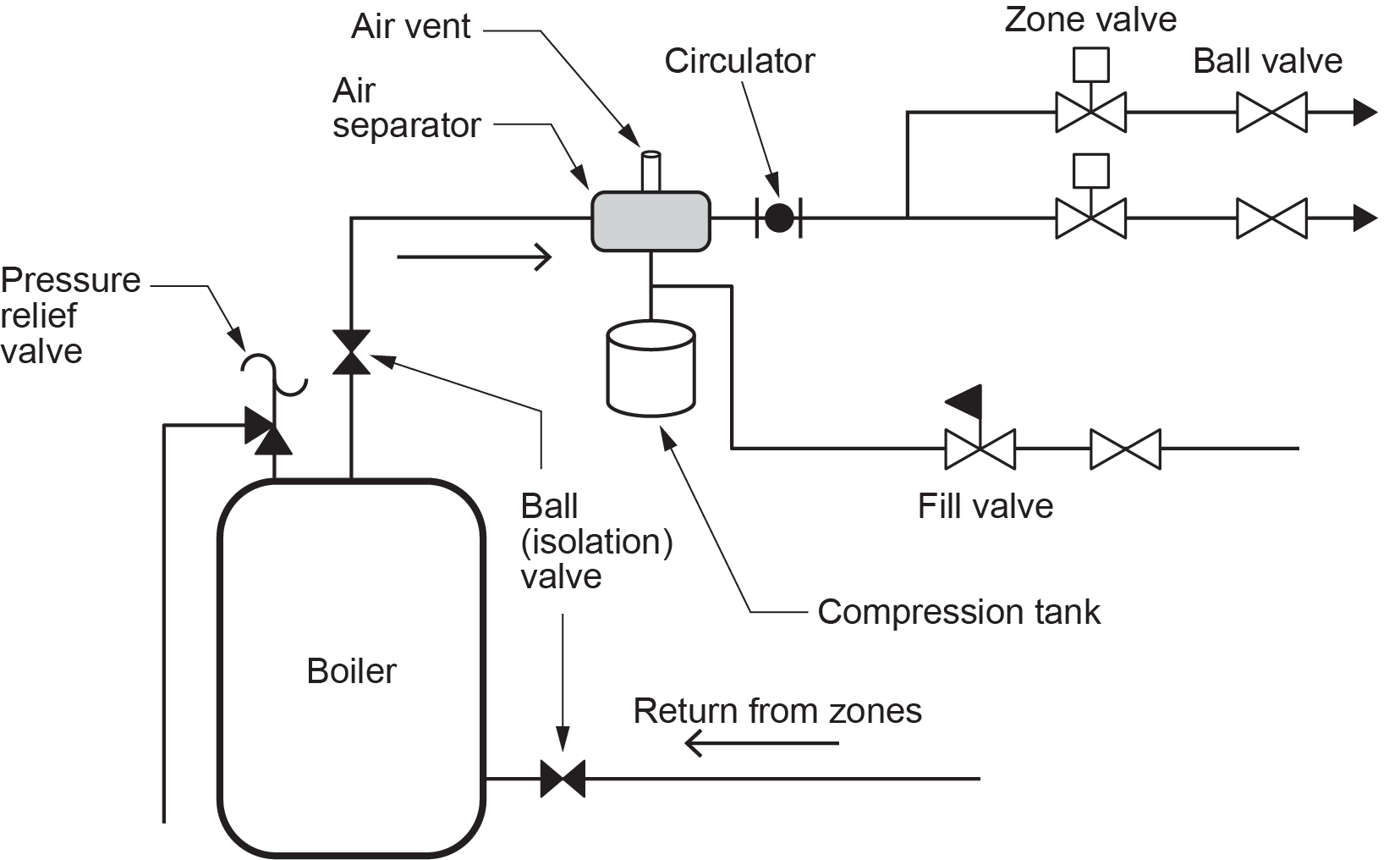
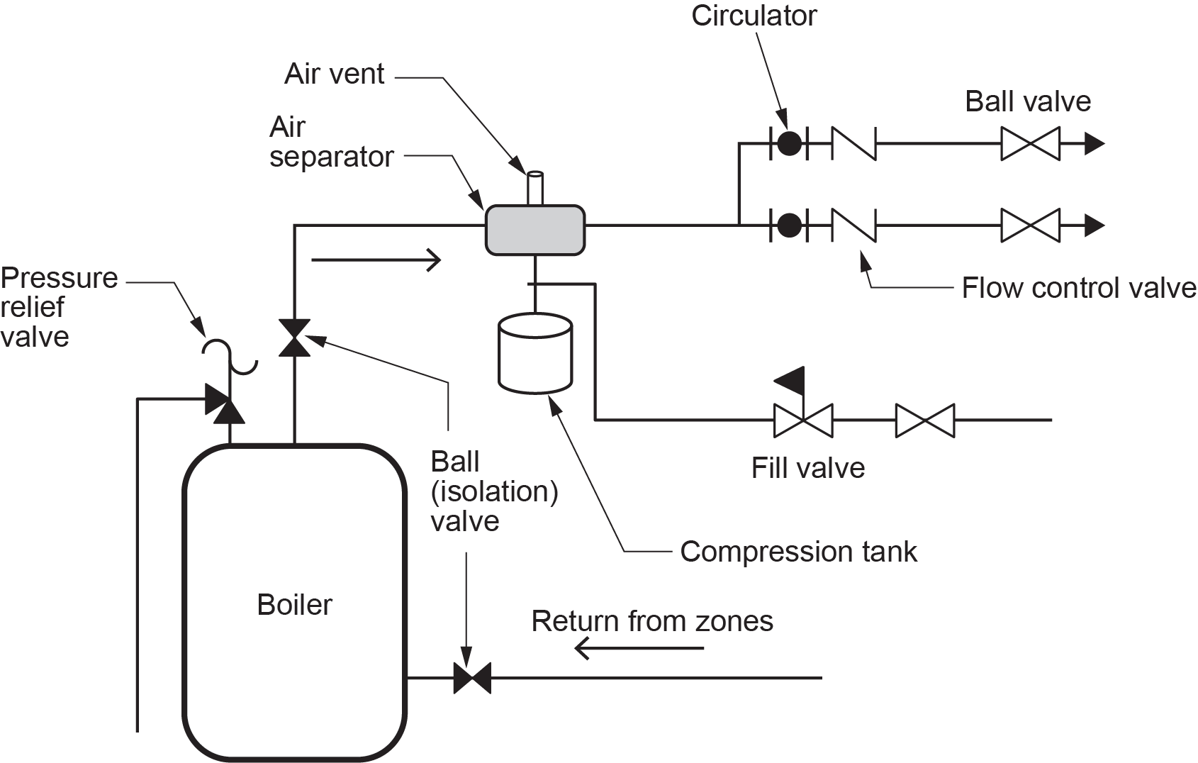
On larger non-residential applications, the pump will often be strong enough to develop a pressure differential that is greater than the static fill pressure. In these cases, it is critical that the pump not be installed immediately upstream of the point of no pressure change. Figure 6a shows a good way to install one pump in relation to other components. Figure 6b shows how to modify this design for two pumps.
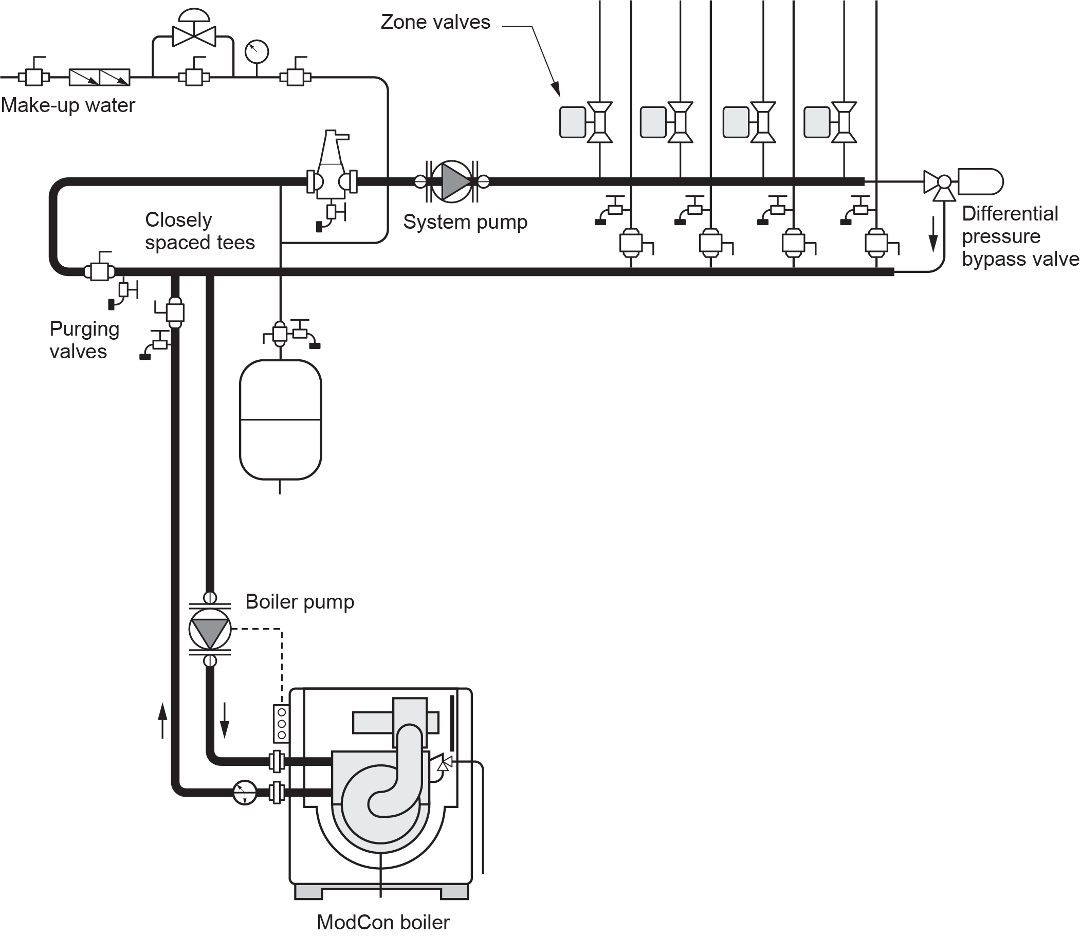
The actual installation of pumps will depend on building and system design. Pumps should also be installed as low in the system as possible. Pumps are less likely to cavitate if there is always enough positive pressure at the pump inlet. Most modern systems will have at least one system pump and a separate boiler pump to ensure the correct flow rate throughout the boiler, regardless of the system flow requirements. Modern condensing boilers will require the boiler pump to be located where it pumps into the boiler return (Figure 7). This is required due to the higher pressure drop created by the condensing boiler’s heat exchangers.
Pump Installation
Circulating pumps will have their inlets and outlets identified; if they are not immediately visible, remember that the inlet water is directed to the eye of the impeller. Circulators can be installed on horizontal or vertical piping, but it is important to check the manufacturer’s specifications to see which orientation is preferred for a particular pump.
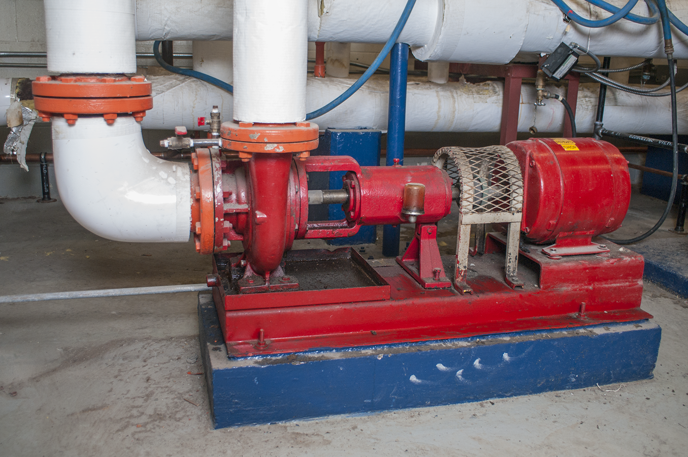
A circulator must be properly supported. For systems up to 50 mm (2 in.) in size, the piping itself is able to support the circulators(s). Larger flanged pumps are normally mounted on a base on a concrete pad on the floor, and piping must be brought down from overhead and run back up again. “Base-mounted” pumps (Figure 8) require special considerations when designing the supply piping and components to avoid creating a swirling action or turbulent flow within the fluid just before it enters the eye of the impeller. Laminar flow is desirable upstream of the impeller.
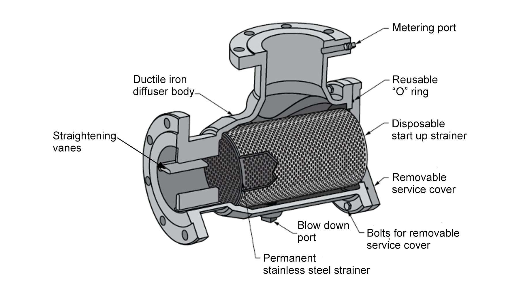
The swirling action creates a “hole” in the water, which causes cavitation of the impeller. Cavitation is the phenomenon where water boils, even at low temperatures, because the air in the solution is being pulled out of the liquid. The impeller can be destroyed fairly quickly due to the air bubbles being compressed and re-absorbed into the water at the impeller’s tips. This can also cause a great deal of noise, ranging from churning and popping sounds to the sound of hammers and bolts being thrown around inside the pump casing. Cavitation can best be avoided by correctly sizing the circulator, not restricting the flow into the impeller, “straightening” the water that enters the circulator, and installing the circulator where the static pressure in the system is highest. If the layout requires elbows close to the pump, special fittings with straightening vanes can be installed on the inlet to straighten out the flow pattern of the water (Figure 9).
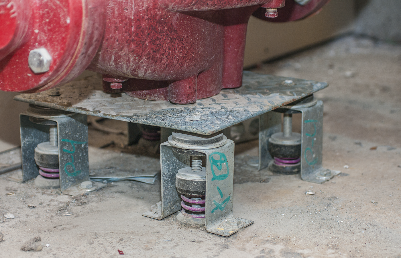
The motor of a three-piece circulator can be quite heavy and cause damage and misalignment if installed incorrectly. When mounting larger pumps, always use vibration mounting brackets (Figure 10). Pumps can sometimes vibrate when operating and, over time, mounting brackets can shift and move if no allowance is made for vibration.
Circulators in a hydronic system may need to be serviced, repaired, or replaced. For these reasons, the ability to both isolate and remove a circulator from a hydronic system is necessary. Isolation is usually done using ball valves, whereas flanges are used to easily remove the pump from the system. Figure 11 shows a small circulator flange kit.
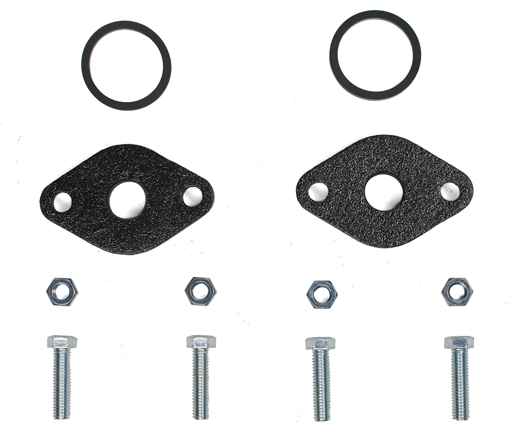
Often, a flange and ball valve can be supplied as one unit, referred to as an isolation flange (Figure 12).
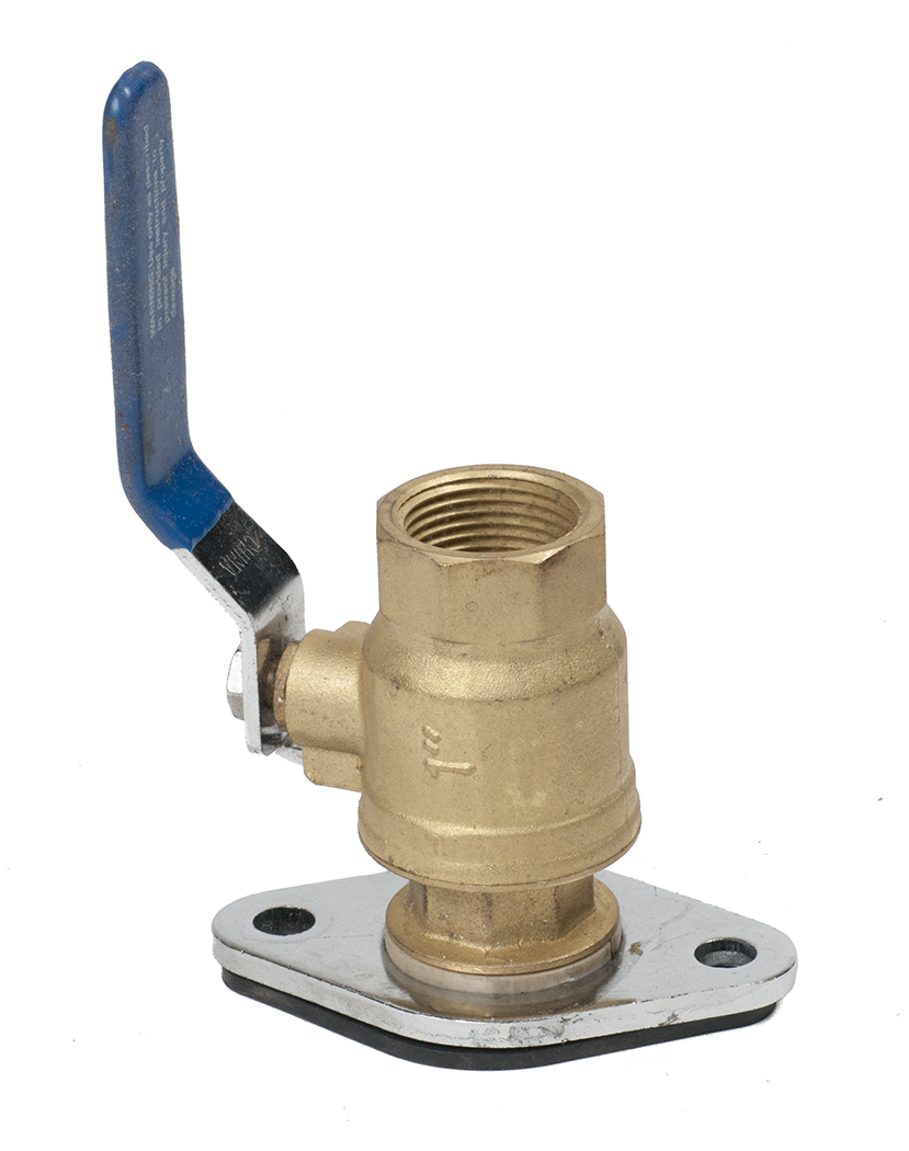
A flange has three parts. One side of the flange is part of the pump assembly. The other side of the flange is attached to the system piping. Between the two flanges is an O-ring or gasket that is compressed to form a seal. The flange parts are tightened together using two or more bolts, depending on the pump size and flange configuration.
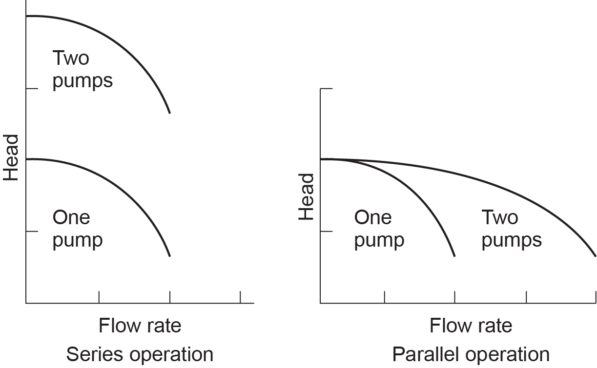
System Pumps in Parallel and Series
It is possible to obtain more flow or higher head pressure by using two pumps. Two circulators of the same size installed in series will approximately double the pressure, whereas two circulators of the same size installed in parallel will approximately double the water flow (Figure 14).
Selecting the Pump
There are two factors that determine the selection of any centrifugal pump: flow rate and head pressure.
The flow rate dictates the amount of heat delivered to the system. The pump must be capable of sending enough heat out to offset the heat losses from design conditions. The amount of water needed to achieve this depends on the system’s temperature drop (ΔT or Delta T). Temperature drop refers to the difference in the temperature of supply water leaving the heating source and return water re-entering the source.
The second factor, head pressure, is the pressure that is needed to overcome the friction within the piping system. The pump must be able to supply a head pressure at least equal to the pressure loss of the circuit that has the most friction. When pressure is referenced, the language of pumps is in feet of head, which can also be expressed as pounds per square inch or psi. One foot of head equals 0.433 psi; inversely, 1 psi. equals 2.31 ft of head.
With the flow rate and head pressure established, the proper circulator can be chosen using the manufacturer’s performance curves, which show the interaction of these two variables. The goal is to choose the smallest pump that can supply the required flow and head pressure.
Determine Temperature Drop and Flow Requirements
Temperature drop refers to the difference in the temperature of water between when it leaves the boiler and when it returns to the boiler. The temperature of the water drops because heat is transferred from the water to the room or zone through heat transfer units. Heat transfer units will have a designed heat output at a particular temperature.
Flow is the rate of water movement through a heat transfer unit, circuit, zone, or system. It is normally measured in US gallons per minute (USGPM). Temperature drop, flow, and BTU/h are closely related. The goal is to choose a flow rate that is neither too slow, causing a greater temperature drop in the water, nor too fast, requiring larger pumps and increased pipe sizes.
A temperature drop of 20°F (11°C) is most commonly used in the heating industry; however, for radiant in floor systems, a temperature drop of 10°F (5°C) is becoming common to achieve a more even surface temperature. It was initially chosen by the Institute of Boiler and Radiator Manufacturers (IBR) so that non-condensing boilers operating at 180°F would not have water returning to the boiler below dew point, which causes condensation and corrosion on the boiler’s heat exchanger surfaces. Dewpoint temperature at atmospheric pressure is approximately 127°F (53°C). Return water temperature to a non-condensing boiler should never be lower than 140°F (60°C).
Calculate USGPM Flow Rate
The formula to calculate USGPM when the BTU/h heat requirement is:
[latex]\color{blue}{\text{USGPM}=\Delta T\times 60\times8.33}[/latex]
Where:
- ∆T is the temperature drop desired, usually 20°F.
- 60 is the number of minutes in an hour.
- 8.33 is the mass in pounds of a US gallon of water.
With this formula, the standard for the heating industry is 1 USGPM = 10,000 BTU/h. (The exact calculation comes to 1 USGPM = 9,996 BTU/h.)
If the flow is too slow, there will be too much temperature drop, causing the heat transfer unit to operate at a lower temperature than the system design, and the building may not be adequately heated. If the flow is too fast, there will not be as much temperature drop, causing the heat transfer unit to operate at a higher temperature than the system design. This can cause the system to overreact to a call for heat, possibly overshooting the room temperature setpoint.
Designers can allow for more or less temperature (∆T) being transferred out of the water, but the number 10,000 is quite convenient for determining flow rates, and designers typically stay with that number.
So, as an example, a building with a heat loss of 66,000 BTU/h will require a flow rate of 6.6 USGPM.
[latex]\color{blue}{66\,000\div 10\,000=6.6\text{ gpm}}[/latex]
Determine Head Pressure
The amount of flow that a pump can supply is inversely proportional to the amount of head pressure it can overcome. In other words, if the amount of system head pressure increases, the amount of flow that the pump can deliver decreases.
Manufacturers publish charts called curves that show the capabilities of their products. For each size of a pump, the chart shows a curve that represents the capacity of the pump. Figure 15 shows a typical pump sizing chart for three small pumps. Once the designer has calculated the system head loss that will be created at the flow rate needed, known as the pump’s “operating point,” it is plotted onto the pump graph. For a pump to be able to deliver the necessary flow, the operating point plotted onto the graph must be below the curve of a chosen pump.
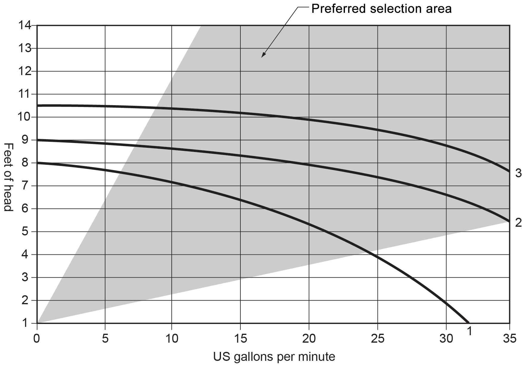
The best overall efficiency of a centrifugal circulator occurs at a flow rate that is close to the center of the pump curve. The two diagonal lines on the chart define the preferred selection area (the shaded part) as determined by this manufacturer. Notice that the flatter pump curves have a wider efficiency flow range.
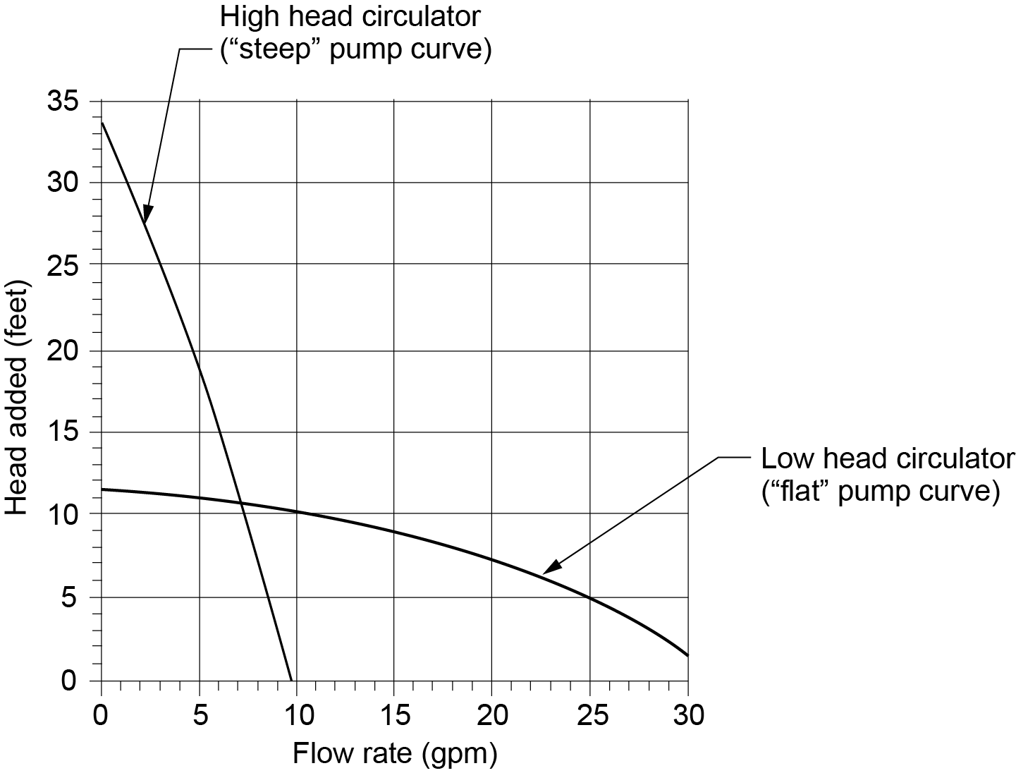
High-Head and Low-Head Pumps
Some circulators are designed to produce relatively high heads at lower flow rates while others produce lower stable heads over a wide range of flow rates. These differences are fixed by the circulator design, particularly the diameter and width of the impeller. The larger the diameter or length of the blades, the higher the pressure; the wider the impeller, the greater the volume. Impeller speed, measured in revolutions per minute (rpm), is the third factor in determining the capacity and pressure of a circulator.
Notice the two pump curves shown in Figure 16. The high-head pump has a steep curve, and the other pump has a flat curve. Interestingly, both of these pumps have the same horsepower motor rating and operate at the same rpm, so the difference between them would be the result of differing impeller designs.
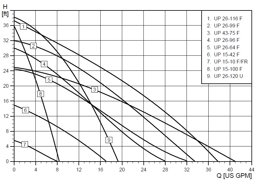
Pump curves (Figure 17) are a very good tool for matching the performance of a circulator to the flow requirements of a piping system. In many cases, the pump manufactures will plot the pump curves for an entire series or family of their circulators on the same set of axes so that performance comparisons can be made (Figure 18). Whenever a hydronic system is zoned using valves, it is best to choose a pump that has a relatively flat curve to limit the increase in differential system pressure as zone circuits are closed.
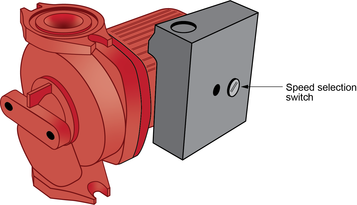
Multi Speed Pumps
Most pump manufacturers also produce multi-speed pumps (Figure 18) in addition to their single-speed varieties. They have a switch that can be set to one of usually three speed positions (Figure 18). Once again, the flow rates and head output of a three-speed pump would be represented on a pump graph for that particular pump. For example, the previously shown Figure 15 chart could represent the curves of the three different pump speed settings of the same circulator. One may think it safest to operate the pump at the highest speed to ensure the system flow required but this would be less efficient than operating at a pump curve that is closest to the required system head.
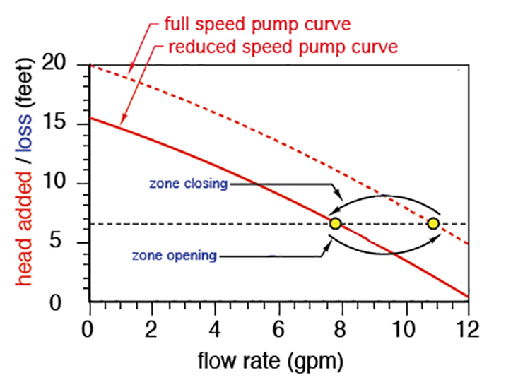
The use of small variable speed circulators has become common, as they help match the changing flow rate requirements of multi-zone valved systems. These variable speed/variable voltage circulators use an input control signal to operate the pump at different speeds and maintain a system pressure differential or setpoint temperature. For example, the pump curve shown in (Figure 20) shows the pump maintaining a set head pressure on a multi-zone valve hydronic system by decreasing its speed and reducing the flow as zone valves within the system are closed. In this situation, the pump’s pressure sensor interprets the increased system resistance head as a sign that less flow is needed in the system.
In addition to pressure regulation, these variable-speed circulators with electronically commutated motors use significantly less electricity when operating at reduced speeds.
This application of variable speed motors is the opposite of the strategy described in Section B-1 for a variable speed forced air fan, where the blower will ramp up its speed to overcome the air flow restriction created as the filter starts to collect dust.
Expansion Tanks
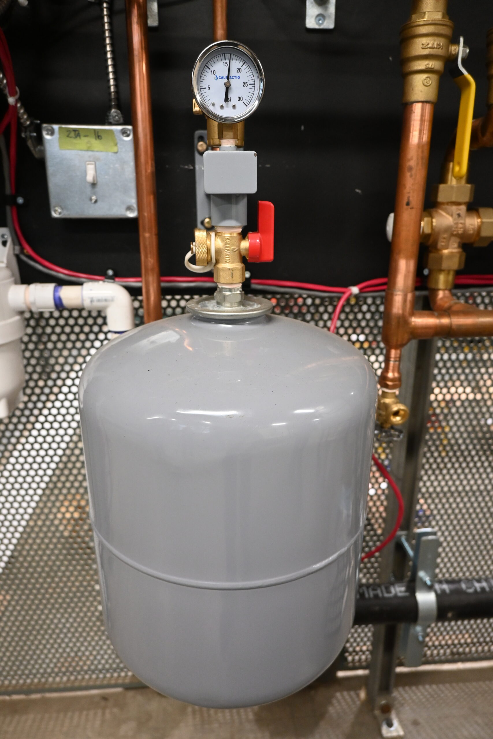
As water is heated, it expands. This expansion must be allowed to prevent an increase in pressure inside a closed-loop piping system. A properly sized and placed expansion tank (Figure 21) allows room for the water to expand and contract.
Calculating Volumetric Thermal Expansion
Most tradespeople have come to know that water expands when it is heated. Just how or why that occurs may be of interest to some, but at the end of the day, most people only want to know what the results of the heating of water are and how to cope with them. Many issues in hydronic heating systems, as well as in domestic potable hot-water systems, are caused by not acknowledging and dealing with the thermal expansion of water before it occurs. The following section will explain how the thermal expansion of water’s volume works.
All forms of matter are affected by heat. Expansion of matter occurs in all directions, but, due to the shape of some objects (e.g., pipe), expansion is more profound in its length rather than in its area or volume. The area of a material, when heated, can increase. The increase in the area of a sheet of aluminum, before being welded, can be calculated and adjustments can be made to minimize warping.
Water is an unusual liquid with unique properties. For most temperatures, water does indeed expand when it warms and contract when it cools. Molecules of water are always in contact with each other. When heat is added to water, the molecules gain energy and move more rapidly, creating more space between them. This translates to the water taking up more space than when it was cooler. There are no more molecules of water than there were before; they simply take up more space, so the water is said to be less dense.
On the other hand, if the temperature of that same amount of water is lowered, the molecules’ vibrations slow down and they occupy less space, so the water’s volume decreases, while its density increases over what it was at the higher temperature. This trend continues down to 4°C (39°F), where the density begins to decrease again. The volume starts to increase because the water molecule (H2O) is starting to crystallize into ice.
In crystallizing, the hydrogen atoms bonding to the oxygen atoms take up more space than they do as a liquid. This expansion can be quite significant, increasing by approximately 9% of its original volume and be powerful enough to split pipe, tanks, and fittings.
The expansion rate of water is considered “non-linear,” meaning that the ratio used to calculate expansion will vary with pressure and salinity (saltiness) as well as with the starting temperature of the water. The amount of this variance is so minimal that, for all intents and purposes, these ratios can be assumed to be constant.
For water, the volumetric expansion ratio to use is 0.00021/°C (0.00012/°F).
What this means is that, for every 1°C (1°F) increase in temperature of a volume of water, measured in whatever units of volume preferred (m3, ft3, in3, cm3, USG, Imp gal, etc.), the volume will increase by a factor of that unit.
For example, if a hot-water heating system is filled with fresh water at 10°C (50°F) and heated to 82°C (180°F), the water’s expansion can be calculated using the following formula:
[latex]\begin{array}{ccc}\color{blue}{\text{Expansion}=\Delta\text{T}\times0.00021\text{ (for °C)}}&\text{or}&\color{blue}{\text{Expansion}=\Delta\text{T}\times0.00012\text{ (for °F)}}\end{array}[/latex]
So, from the information above, for whatever the starting volume, the water would expand:
For Celsius or Kelvin:
[latex]\color{blue}{72^\circ\text{C}\times0.00021=0.015\text{ times or }1.5\%\text{ its original volume}}[/latex]
For Fahrenheit or Rankine:
[latex]\color{blue}{130^\circ\text{F}\times0.00012=0.015\text{ times or }1.5\%\text{ its original volume}}[/latex]
Note that it does not matter which expression of temperature is used (Celsius/Kelvin or Fahrenheit/Rankine), only that the expansion ratio chosen marries up with its proper corresponding units of temperature.
Therefore, using the example calculation above, if the starting volume of the water is 20 gallons, the water would end up occupying:
[latex]\color{blue}{20\times0.015=20.3\text{ gallons of space}}[/latex]
If the starting volume of the water was 20 m3, it would occupy 20.3 m3 of space, and so on.
Why the Need for Expansion Tanks?
Hydronic heating systems work because they are completely filled with water with no air pockets. Air causes blockage of flow because a pump (circulator) is incapable of moving anything but a liquid. Thermal expansion of the system fluid as it heats up causes an increase in the space that the system water needs to occupy. If the extra volume in the system’s water is not given a place to push into, the pressure in the system will rise sharply and likely trip the pressure relief valve mounted on the boiler.
When some hot-water heating systems are not providing heat, the entire system may cool from an operating temperature of about 82°C (180°F) to the temperature of the surroundings. The result is an approximate 1.5% decrease in the volume of the water and a slight decrease in the volume of all the components (boiler, heat transfer units, valves, and piping). Similarly, when the system heats up again, the water and the components increase in volume by roughly 1.5%.
A properly sized and placed expansion tank allows room for the water to expand and contract without causing a significant change in system pressure.
The water expands and contracts much more than the components that contain it. As stated earlier, when the system heats up to operating temperature, enough pressure is created to cause the pressure relief valve, which is installed directly into the boiler, to do its job. The relief valve opens enough to keep the pressure in the boiler to no more than 30 psig, which is the maximum pressure that any cast-iron boiler is allowed to be subjected to.
Once the call for heat ends and the boiler energy source shuts off, the water in the system cools. Its volume shrinks and the system pressure drops, sometimes to a value below the initial fill valve setting, which is typically 12 psig for most residential houses. Once this occurs, the automatic fill valve does its job. It opens and adds water to the system to re-establish the 12 psig setpoint pressure. When the thermostat calls for heat, this cycle of discharge/fill is repeated.
The net effect of the relief valve discharge/fill valve open sequence is that there is a constant introduction of fresh water into the system. Fresh water contains oxygen in solution, and the oxygen, while being beneficial to most living things, will kill a hydronic system that has ferrous components in contact with the system water.
When a system is initially filled, the dissolved oxygen migrates right away to any system equipment that contains iron and forms rust. The ferrous components, however, are not usually affected by this small bit of oxidation because it is not constant. Once the oxygen level in the water drops because it has combined with iron, it is no longer a rust-causing threat. This is why commercial fire protection systems made of steel pipe will last decades without rusting and falling apart. Aside from periodic tests every three to five years, no fresh water enters these systems, and rust is not an issue.
Any hydronic heating system that has water added to it on a continual basis is a prime candidate for rusting from the inside out. The ferrous components are circulators, boilers, and any other iron-bearing parts that are in contact with system water. This is the reason for the expansion tank.
Conventional Expansion Tanks
The earliest hydronic systems had an expansion tank mounted in the attic. The tank was the highest point in the system and was open to the atmosphere. The water level in the tank created the head pressure for the system’s operation. Because it was connected to the piping off the top of the supply main, any air liberated from the boiler water by the heating process travelled easily upward and was released into the tank and subsequently dumped into the atmosphere through the vent.
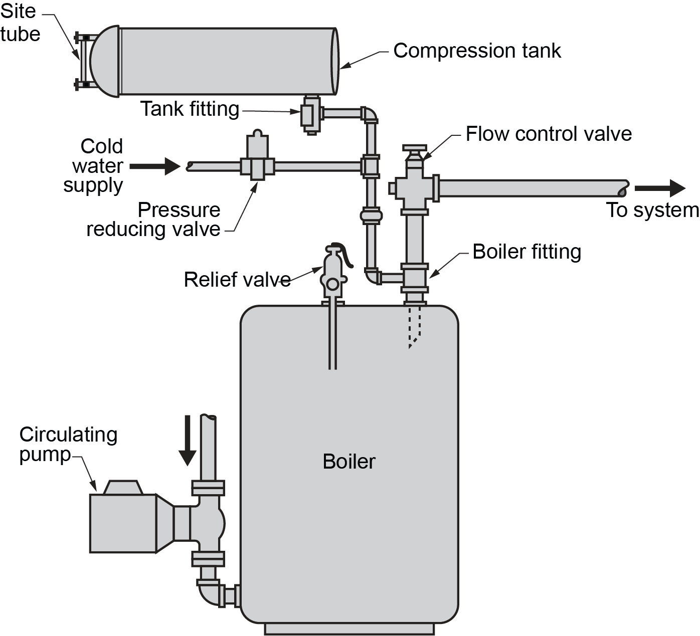
As the system water heated up and expanded, the extra volume pushed upward into the expansion tank, sometimes overflowing out onto the roof. Over time, the attic location proved to be problematic, so the expansion tank was relocated into the basement and mounted just above the boiler. It also had to be a closed tank because it was no longer the system’s high point (Figure 22).
The early tanks were of either galvanized or copper construction. They were installed horizontally and had a vertical glass tube mounted on one end between two valved fittings threaded into the tank. This “sight tube” was a visual indicator of the water level in the tank. When the tank was mounted in the attic, seeing the water level was not really necessary because the system was filled until water spilled through the overflow onto the roof. As long as water was present at some level in the tank, the system operated as it should.
When the tank was relocated to above the boiler in the same room, the sight tube became a much more important component.
When filling the system initially, water was introduced through the cold-water makeup line to fill the system to approximately 12 psig (for most systems). Any trapped air migrated to the system’s high points, where it had to be bled by opening properly located air vent valves or, as an alternative to that, by “power purging,” which will be discussed later. Water also pushed into the expansion tank, a high point on its own, and filled it to approximately [latex]\tfrac{2}{3}[/latex] to [latex]\tfrac{3}{4}[/latex] its volume. The air trapped above the water was compressed to the same pressure. This air was not bled off; it became the “cushion” that accommodated the expanded water volume from the system.
These rather large tanks easily accommodated the extra volume of heated water. The air cushion acted like a spring that pushed the water back into the system piping when the boiler was not firing, and the water cooled and contracted. The system’s volume was able to expand and contract without appreciably affecting the pressure in the system. The relief valve stayed un-tripped, and the cold water makeup valve stayed closed. Hydronic systems were not subjected to the forces of oxidation, and life was good — for a while.
It was soon discovered that air, once bled from a body of water, has the ability to be re-absorbed over time. Checking the sight tube periodically led to the discovery that the volume of air trapped above the water became less and, at some point, its volume became so low that when the boiler fired, the pressure created was once again enough to trip the boiler’s pressure relief vale. This was due to a lack of air space in the tank. This phenomenon is known as “waterlogging.” A waterlogged tank will not have enough volume to accommodate or accept the extra volume of water, so the pressure rises to levels that it should not reach.
The solution then is to drain the tank and refill it to re-establish the proper water-to-air ratio. When these conventional tanks were in use, two special fittings were commonly installed along with it.
One was a tee with an internal dip tube meant to be installed on a top-outlet boiler. Air liberated from the water through the heating process tended to collect at the top of the boiler. Once there, it would exit the boiler into the system supply piping and end up somewhere in the system, possibly causing circulation issues. The dip tube in the aptly named “boiler fitting” allowed system water to leave at a slightly lower point than where the air collected. The air then left the boiler through the same fitting but through a space around the dip tube and out the branch of the tee, where it was directed to the expansion tank through another special fitting, the “tank fitting.” The tank fitting also had a tube located within it that allowed air or water to be bled from the tank without having to shut off or disconnect the tank from the system piping. The “conventional” tank, with its specialized fittings, is now considered old school and is not used much anymore, other than possibly in larger commercial systems, where an operator is available to monitor the water level in the tank.
Bladder or Diaphragm Tanks
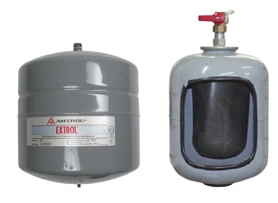
Conventional expansion tanks were typically large because they had to allow a reasonable length of time between replenishment of air due to waterlogging. For a number of decades now, manufacturers have been producing tanks with a rubber diaphragm within them (Figure 23) that physically prevents water and air from being in contact. This style of tank eliminates the possibility of waterlogging unless the diaphragm material tears or the Schrader valve leaks and allows the air pressure to escape. They are pre-charged with air, which surrounds the diaphragm, with the system water filling the diaphragm’s interior space. Besides a lower cost factor to purchase and install, some of the other benefits of this newer style of tank are:
- The tank is now normally installed under the system piping, eliminating the need to support it above the boiler. It now “hangs” from the piping.
- The pre-charged tanks are typically much smaller than their old counterpart now that extra space to accommodate waterlogging is not required.
- With air surrounding the diaphragm, there is no contact between system water and the steel of the tank, so tank corrosion is essentially negated.
Point of No Pressure Change
The location in the system piping where the expansion tank connects to the system is known as the point of no pressure change, which was covered earlier in the “Pump Location” section. Make sure to read the information there thoroughly, as it has a great effect on pump placement in every hydronic system.
Selecting Expansion Tanks
Certain variables must be considered to properly calculate the amount of expansion that will take place and to ensure that the tank will operate correctly for that system, including the following:
- Total volume of water in the system
- Minimum system temperature
- Maximum system temperature
- Minimum operating pressure
- Maximum operating pressure
- Presence of glycol in the system
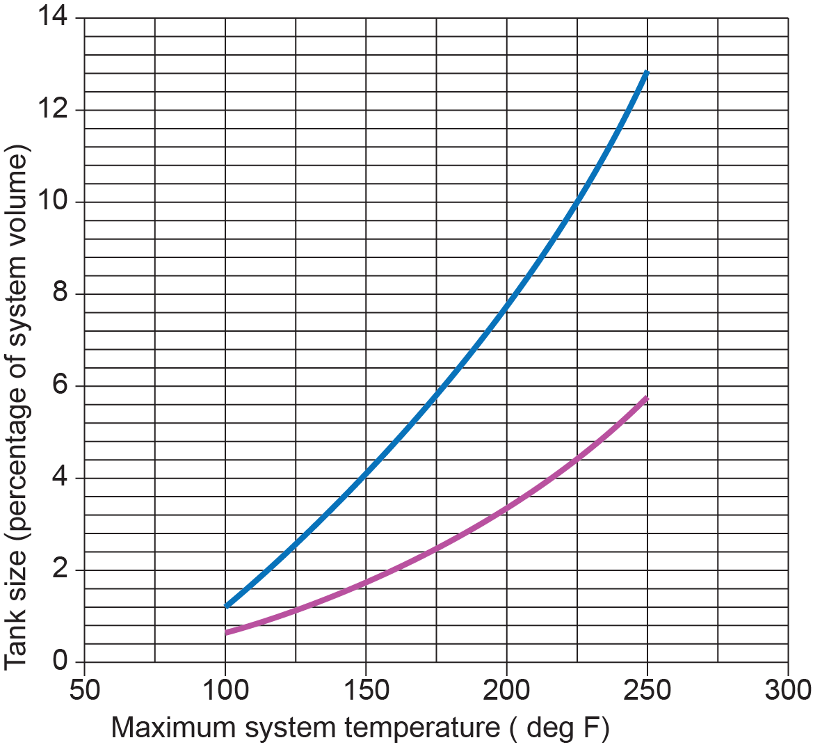
This information is compared with manufacturers’ information and tank specifications to size the expansion tank. Figure 24 is an example of one such graph used to calculate the amount of expansion that takes place for different system temperature changes.
Expansion tank sizing will be covered in more detail in Level 3 Plumbing Apprenticeship.
Air Removal
Every hydronics installer will eventually come across the issue of no or very little flow through the system. Although there can be many reasons for this, one of the most common is air trapped within the system. All water contains air in solution, and when that water is heated up, the air slowly separates and collects at high points. These air bubbles move around the system, creating all types of problems. The job of designers and installers is to create a system that is able to remove the air before it becomes a problem.
Problems Created by Entrapped Air
There are several problems that can be traced to excessive air within hydronic heating systems:
- Noisy flow
- Increased corrosion
- Poor or possibly no flow
- Poor heat transfer
- Cavitation leading to circulator damage
For these reasons, air removal must be a priority in system design.
Air Removal Devices
Air removal devices can be categorized by where they are placed in a system.
Because heated air tends to rise, it makes sense to place some type of air vent at the high points in a system. For this reason, these vents are referred to as “high-point vents” or simply “air vents.” Typical locations for such vents are at the top of each heat emitter, at the top of distribution risers, or wherever piping turns downward following an upward or horizontal run. High-point vents are particularly useful for removing air immediately after the system has been filled with liquid.
The second type of air removal device is the central air separator. When water passes through a boiler, it is heated, which releases air as bubbles. These air bubbles will then work their way around the piping system until they find somewhere to collect and create issues. A central air separator is located on the supply piping leaving the boiler because air is most easily removed from water wherever it is hottest and slowest.
Manual Air Vents
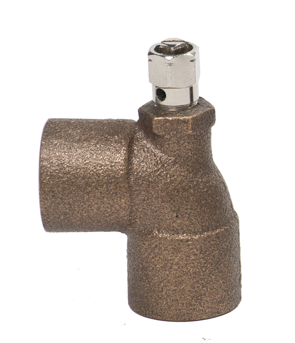
The simplest type of high-point vent is a manual air vent (Figure 25). As the name implies, the manual air vent requires an operator to both open and close the vent. These vents can sometimes be referred to as coin vents or bleeders. Manual air vents are installed at locations where small amounts of air will have to be eliminated during startup and maintenance, but not where large amounts of air are likely to accumulate during normal operation. The most common location for manual air vents is at the downstream (return) end of heat transfer units. Manual air vents have a needle-type stem with either an insulated hand wheel or simply a slot in the end for a screwdriver or a coin.
Great care must be taken to ensure that these types of vents do not leak after being used because they have been known to leak small, unnoticed amounts of water over long periods; this can cause widespread water damage in wooden buildings.
Automatic Air Vents
Automatic air vents open automatically in the presence of air and close automatically in the presence of water. There are automatic disk and automatic float air vents. Automatic air vents should be installed together with isolating valves so that repairs or replacement can occur as required.
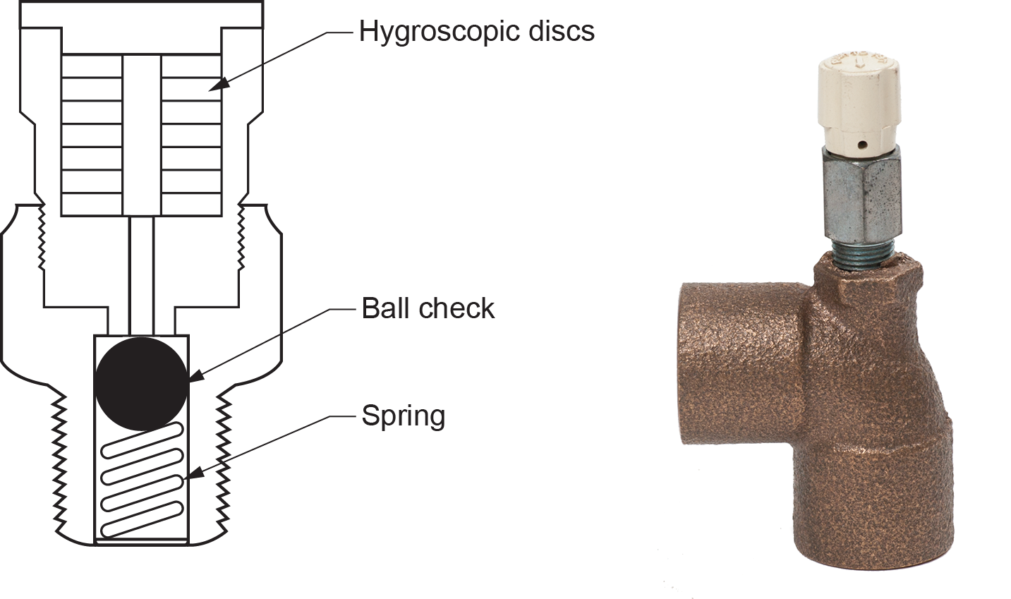
An automatic disk air vent (vent valve) contains one or more water-sensitive disks (Figure 26). These disks swell up in the presence of water and shrink in the presence of air. This effect is used to open and close a small valve that automatically releases any enclosed air. Automatic disk air vents are very slow devices, but they do not drip when operating. They can be manually opened to let more air out when you fill the system, and they can readily cope with the small amount of air that is released when water is heated. They can come equipped with a ball check to enable removal and replacement of the air vent while maintaining the liquid within the system.
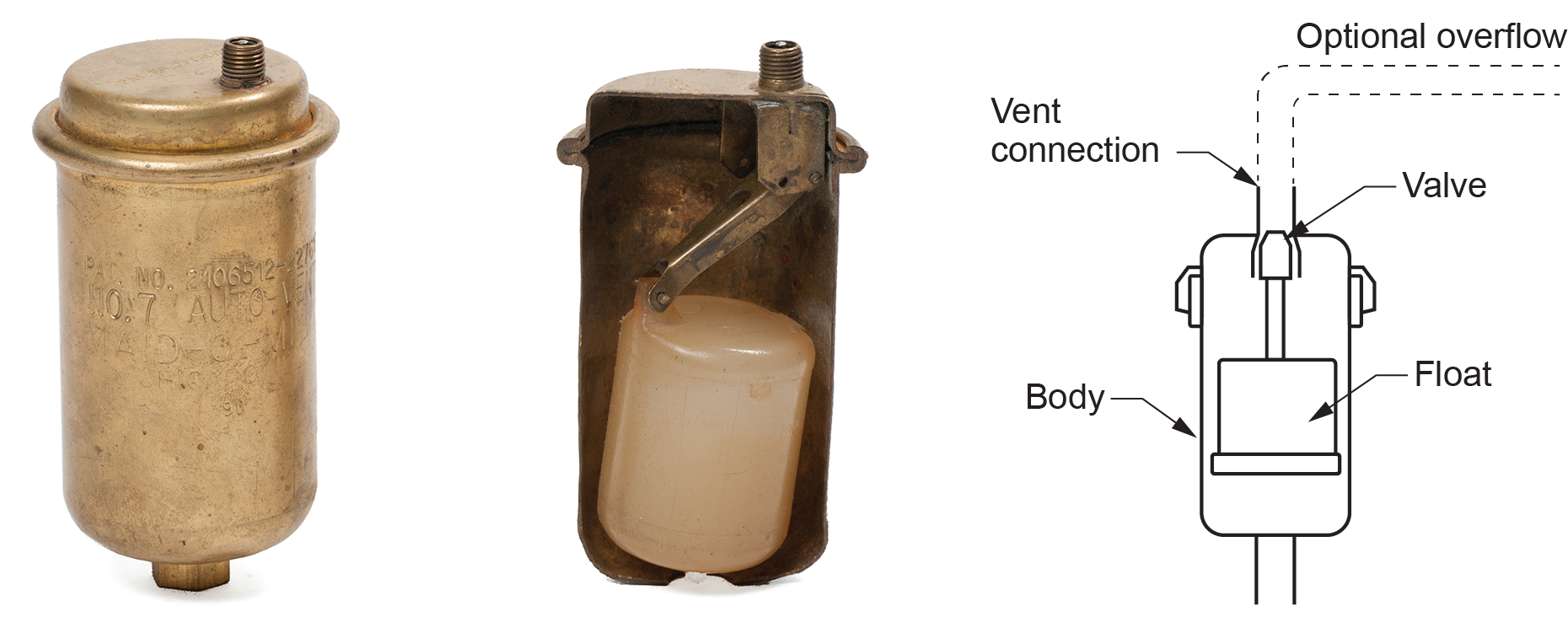
An automatic float vent (Figure 27) works on the principle of buoyancy. The device contains an air chamber, float, and air valve. The float moves up and down based on the presence of water in the chamber. If there is no water in the chamber, the float will drop down, opening the air valve. This allows the air in the chamber to escape. As the air escapes, water from the hydronic system begins to fill the chamber and lift the float up. This causes the air valve to close. There are times during this process when a small amount of water also escapes, but generally, this is not an issue.
Automatic air vents have a [latex]\tfrac{1}{8}[/latex] in. threaded connection on the Shrader valve, similar to that found on a car’s tire. An adapter and overflow tubing can be connected to the air vent, and any discharge of water during its operation will be directed to a safe location. This is especially helpful in situations where the automatic vent is located high overhead or where it may not be readily visible. The threaded vent connection comes equipped with a threaded cap. It is important to leave the cap partially unscrewed or the air outlet will be sealed. Install these vents in the vertical position, with the vent connection pointing up.
Air Purgers or Air Scoops
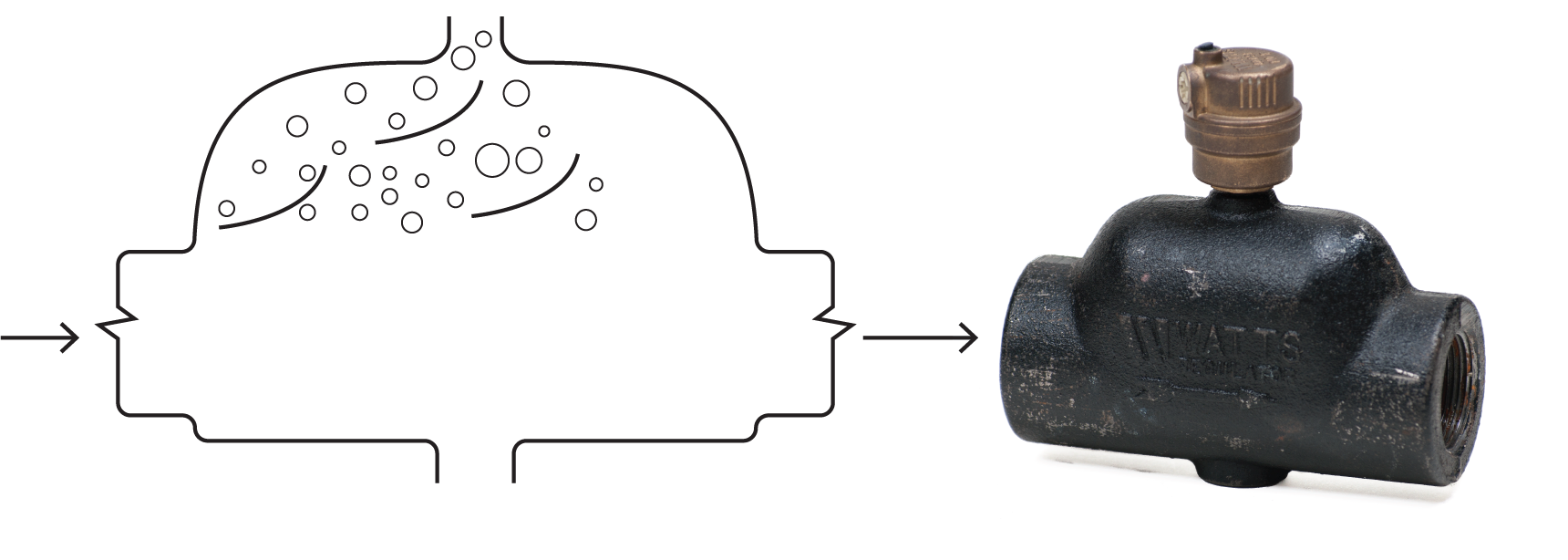
Air purgers (also called air separators or air scoops) remove the air in water by separating it from the water and venting it outside the system. An air scoop consists of a one-piece, cast-iron chamber with two passages containing contours and baffles (Figure 28).
As a mixture of water and air flows through these passages, the air is separated and then vented to the atmosphere through an automatic float air vent. Air scoops are installed horizontally on the main as close to the boiler as possible. However, to optimize effectiveness, 18 in. of straight horizontal piping is required on the inlet side to achieve the desired laminar flow. The enlarged cross-sectional area causes a velocity drop through the air scoop that allows more time for entrained air bubbles to float up to the air vent. If a diaphragm compression tank is installed, it may be connected to the bottom of the air scoop.
Microbubble Resorbers
Another device similar to an air scoop and serving the same purpose is a microbubble resorber (Figure 29). Microbubble resorbers are very effective in removing all types of air from the system. They have many small vertical wires or screens inside that create areas of reduced pressure on their downstream side. The low pressures encourage dissolved air to come out of the solution as microbubbles coalescing and rising along the wires. The microbubbles accumulate in the upper auto air vent and are released from the system. Microbubble resorbers are the preferred choice for air removal devices, especially in situations where there is not enough room to install 18 in. of straight horizontal piping on the inlet side.
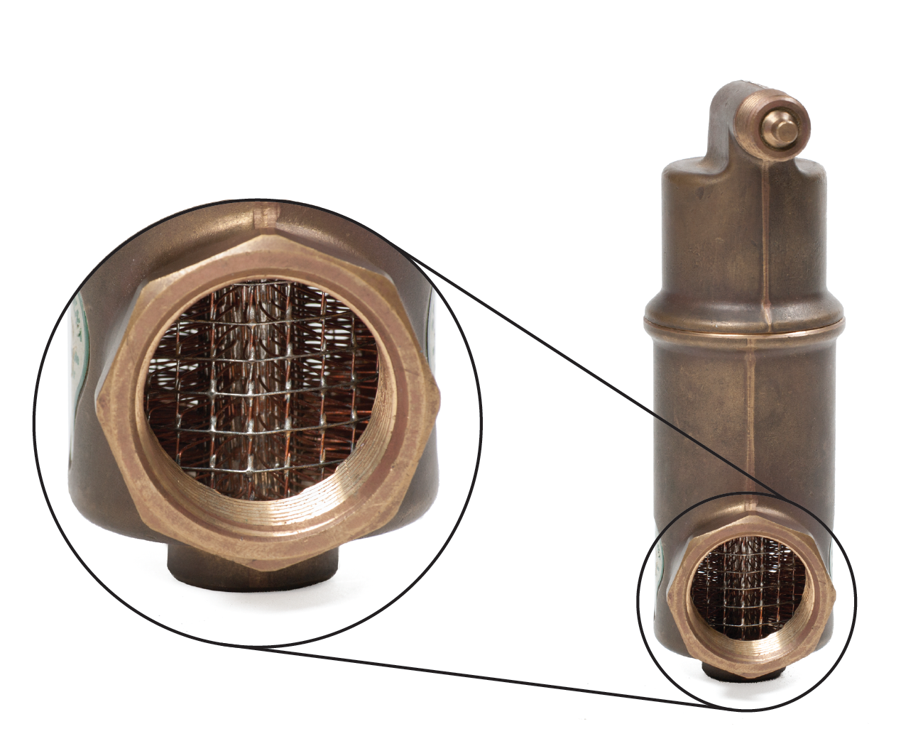
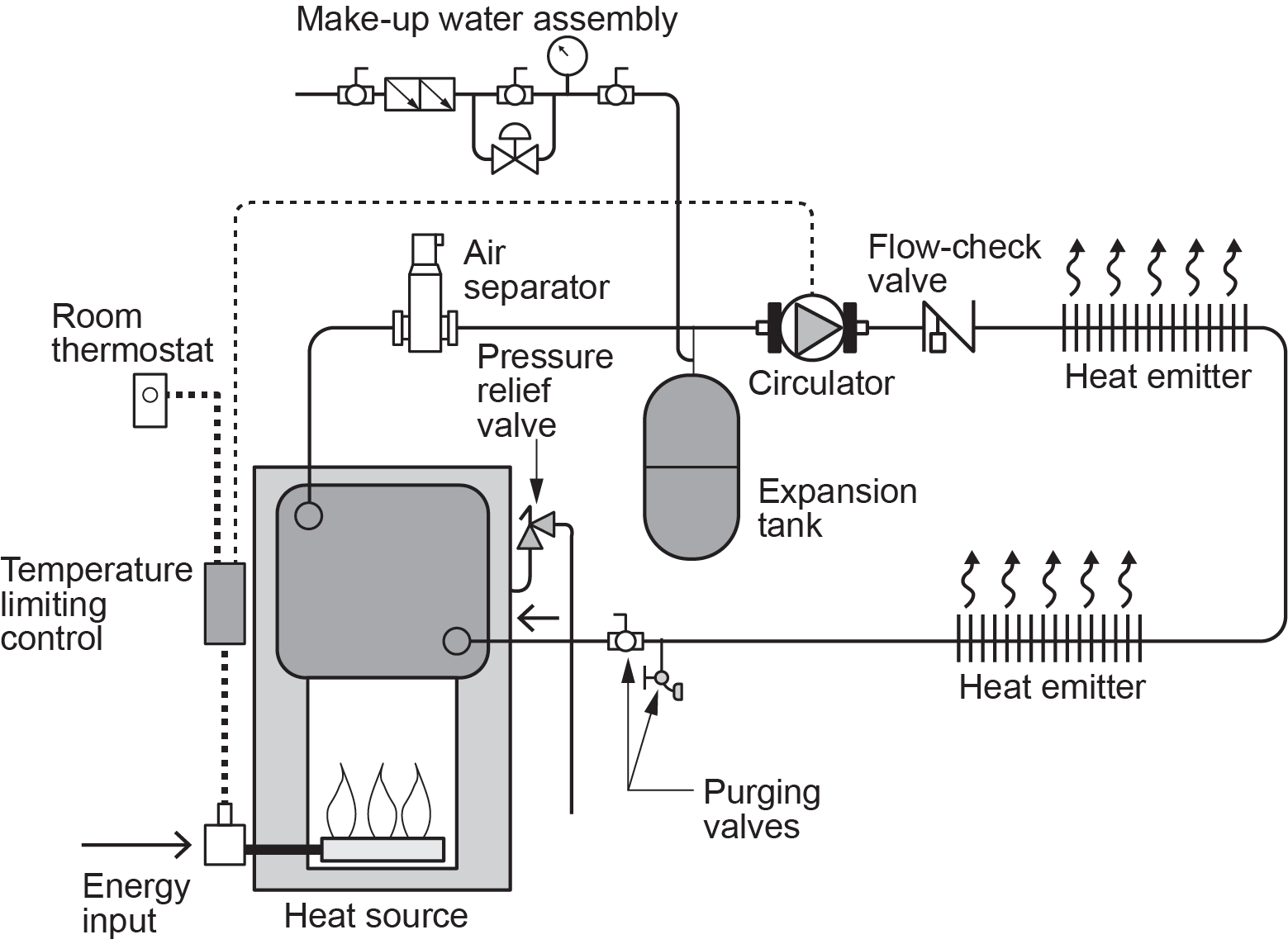
Either an air purger or microbubble resorber will be located on the supply piping as it leaves the boiler, where the water is hottest and most easily released from the solution. Figure 30 shows a typical location of an air separator within a system.
Water Quality
The ideal water for use in hydronics systems would contain very little physical or chemical contaminants. Treatment for water quality can be divided into two categories:
- Physical water quality
- Chemical water quality
Physical water quality treatment captures and eliminates air and dirt from the system. Chemical water quality modifies or eliminates harmful chemical substances in the system water.
Dirt Removal
The ideal heating or cooling system would be dirt-free. But, in reality, there are many ways that dirt and sediment can get into a hydronic system. The presence of dirt can cause serious problems including:
- Circulator damage
- Reduced heat transfer due to fouled surfaces in heat exchangers
- Increased internal flow erosion
- Blocked sight glasses on flow meters
- Clogging and malfunction of flow meters, zone valves, balancing valves, check valves, vents, and thermostatic radiator valves
There are three common methods of removing dirt and debris from hydronic systems:
- Initial flushing and cleaning
- Basket strainers
- Dirt separators
System Flushing and Chemical Cleaning
An assembled system must be flushed to remove debris, such as solder balls, metal chips and shavings, casting sand, sawdust, drywall dust, insects, paper labels, and dirt, that entered the piping during transportation, storage, or handling on the installation site. Chemical cleaning removes oils and greases from thread cutting oil, soldering flux, or small amounts of machining oil remaining inside system components.
The preferred method for the initial chemical cleaning of the inside of a hydronic system is by circulating a hydronic detergent mixed with hot water through the system. When the cleaning solution has been sufficiently circulated, it is drained from the system, carrying the dissolved oil and grease residue with it.
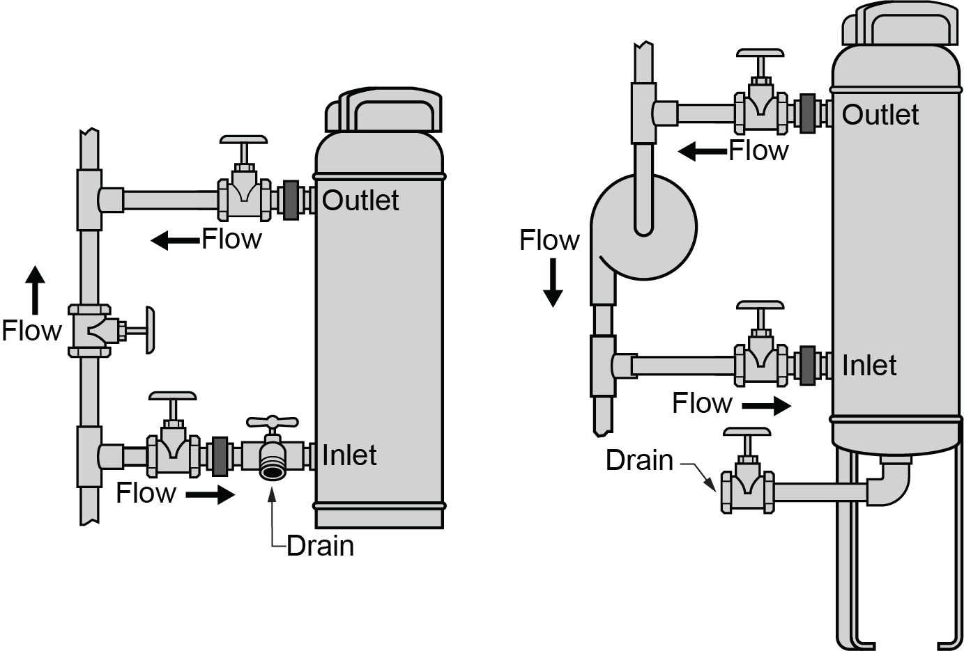
To perform either initial flushing or chemical cleaning procedures, the system must be equipped with the appropriate valves (Figure 31) to add fluid and remove both air and dirty fluid.
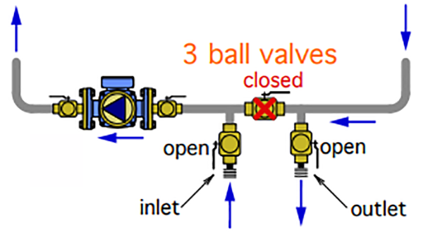
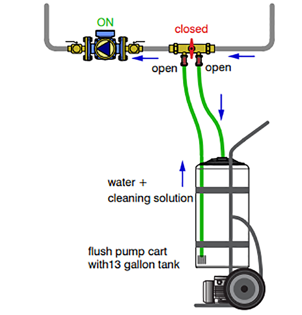
When possible, purging valves should be located upstream of components such as circulators and heat exchangers. This minimizes the chance of flushing debris in the piping through these components. After the initial debris flushing, a chemical cleaning solution can be added to systems by use of a flush pump cart connected to the purge valves (Figure 32).
Other methods for performing the initial system purging using the makeup water connection will also be discussed in B-4.2 Hydronic System Valves.
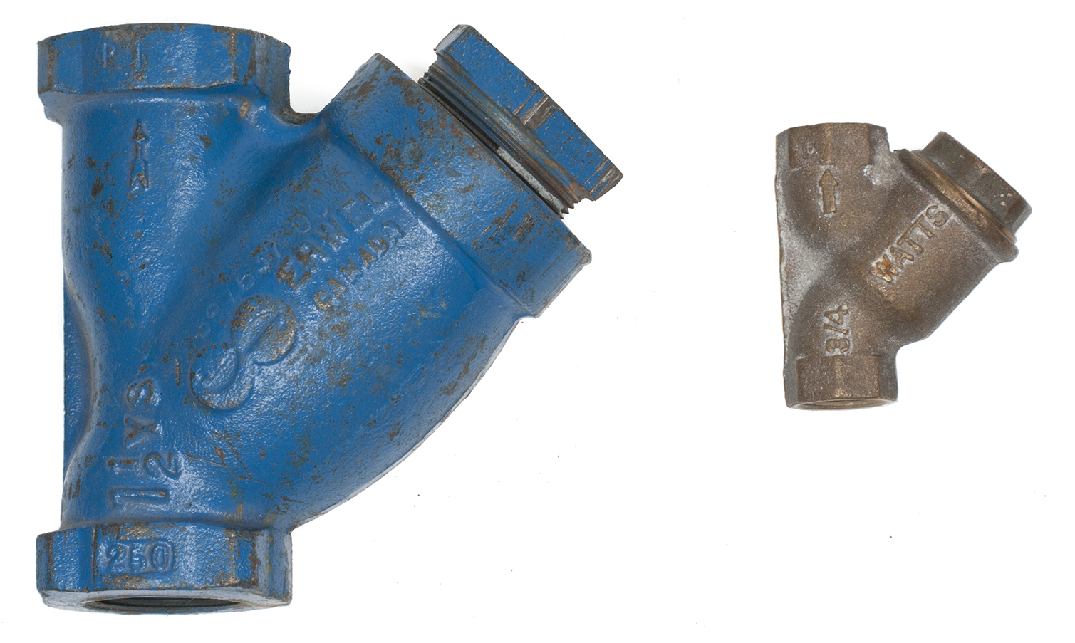
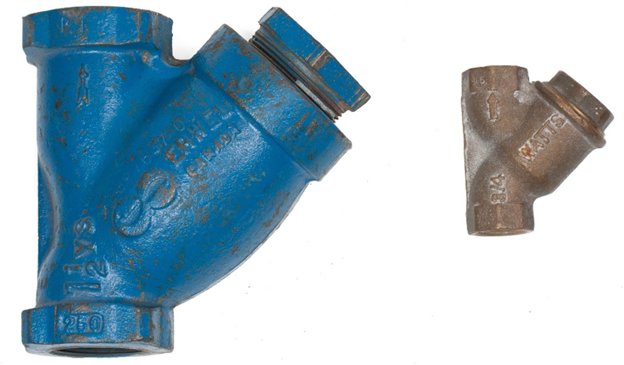
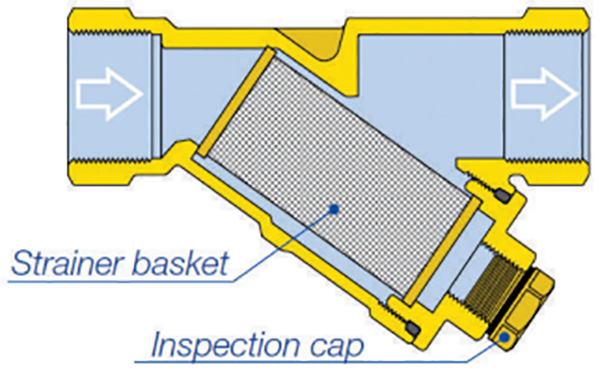
Strainers
Basket strainers, also known as Y-strainers (Figure 33), trap dirt within a mesh basket made of stainless steel or brass. A strainer should be installed just upstream of the pump in order to protect the pump. It is important to maintain the strainer so there is not an excessive accumulation of debris on the inside the strainers basket, which will restrict flow. The strainer normally has a tapping with a plug, or a blow-down valve can be installed to allow for easier cleaning. A blowdown is a drain point used to flush out sediment captured in the strainer.
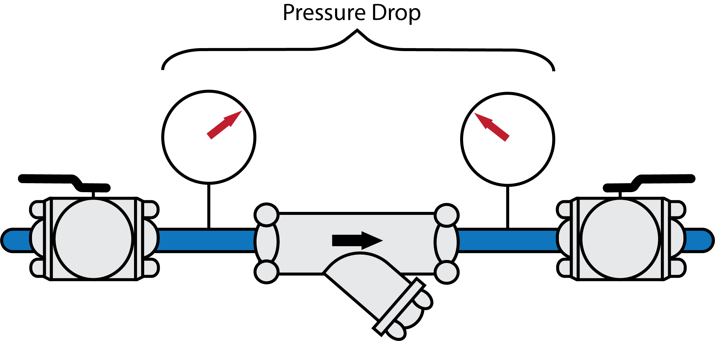
On commercial systems, pressure gauges may be installed to monitor the pressure drop across a basket strainer (Figure 34) and determine when cleaning is needed.
Dirt Separators
Many dirt separators are also air vents, as they use the same principle as microbubble resorbers. As the water passes through the low velocity chamber, dirt particles collide with the coalescing media and settle to the bottom chamber. A valve at the bottom of the chamber is used to periodically flush out accumulated particles. Notice that the unit shown in Figure 35 has four pipe connections as it is also a hydraulic separator. The concept of hydraulic separation will be discussed in B-4.3.
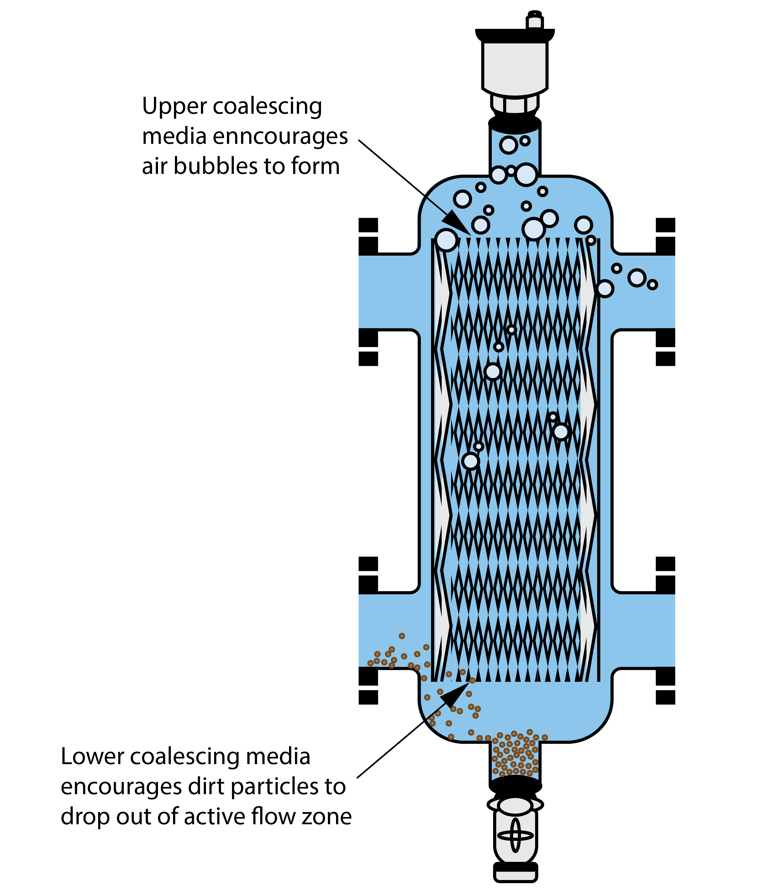
Because the screens and wires do not accumulate sediment, like a Y-strainer, they do not create an increased resistance within the piping system. Many hydronic systems contain cast iron or steel components, which form iron oxides. As iron oxide particles are attracted to magnetic fields, they tend to accumulate in the circulator due to the motor’s magnetic fields. The ability of a dirt separator to capture iron oxide particles is enhanced by adding a powerful magnet on or within the separator. When the magnetic portion of the separator is removed, the iron oxide particles along with other debris can be flushed out from the lower bowl of the separator.
Chemical Treatment
Residential hot-water heating systems do not normally require the periodic addition of chemicals, but commercial and industrial hot-water heating systems may require chemicals to:
- Degrease the system
- Inhibit corrosion
- Lubricate components
- Prevent freezing
Degreasing agents are used to clean the system. Corrosion inhibitors prevent rust from forming on interior surfaces. Lubricants help valves and other components function smoothly. Glycol prevents freezing.
Degreasing agents, corrosion inhibitors, and lubricants are added to the system through a pot feeder (Figure 37). The pot feeder is made of cast iron or steel and can hold several litres or gallons of chemical solution. The pot feeder is installed at a convenient location on one of the mains, typically in the boiler room. The pot feeder is installed on a short bypass to the main with an isolating valve at either end.
When a chemical solution needs to be added to the system, do the following:
- Isolate the pot feeder by shutting off the inlet and outlet valves.
- Drain the pot feeder of residual fluid.
- Open the pot feeder lid.
- Clean the pot feeder tank.
- Close the drain valve.
- Add the required solution.
- Vent excess air from the pot feeder.
- Open the isolation valves.
Give the added chemicals a few minutes to circulate and mix with the system water, then repeat the process until the required amount of chemical has been introduced into the system. Test kits are available for any water characteristics being adjusted.
Degreasing agents must be flushed from the system after they have served their function, whereas corrosion inhibitors and lubricants are allowed to remain in the system.
Glycol solutions are added to an empty system, although not through the pot feeder. A premixed glycol solution can be added to a system with the use of a pump cart, as previously shown. Systems that use glycol solutions rather than water will require a larger compression tank suitable for glycol, a stronger circulating pump, and a higher level of backflow protection.
Low-Water Cutoffs
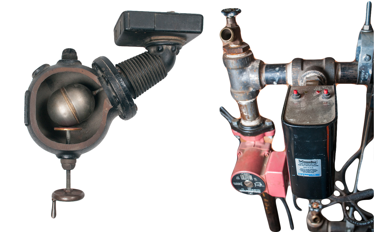
Another safety device required on some hot-water boilers and all steam boilers is a low-water cutoff (LWCO). A low-water cutoff is installed as a safety guard against a low-water condition in the boiler. If the water in the boiler gets to a dangerously low level, an electrical circuit to the energy source (typically the gas valve) is interrupted and the burner is shut off. LWCOs can either be of a float type (Figure 38) or a probe type. The float type uses a float ball connected to a switch, and the probe type is inserted into the boiler through a tapping at the lowest safe water level. It uses the conductivity of water to complete or break an electrical circuit, which allows the burner to keep firing or shuts it down.
 Self-Test B-4.1: Hydronic Distribution System Components
Complete the chapter Self-Test B-4.1 and check your answers.
If you are using a printed copy, please find Self-Test B-4.1 and Answer Key at the end of this section. If you prefer, you can scan the QR code with your digital device to go directly to the interactive Self-Test.

References
Caleffi Hydronic Solutions. (2014, July). Figure 3-10, Y-Strainers, Separation in Hydronic Systems [digital image]. idronicsTM (15), 2014, 19. https://idronics.caleffi.com/magazine/15-separation-hydronic-systems
Caleffi Hydronic Solutions. (2015, January). Figure 6-8, Constant differential pressure control, Circulation in hydronic systems [digital image]. idronicsTM (16), 2015, 43. https://idronics.caleffi.com/magazine/16-circulation-hydronic-systems
Caleffi Hydronic Solutions. (2016). Figure 4a, 3 ball valves, Water quality in hydronic systems [digital image]. idronicsTM (18), 2016, pp. 19 & 22. https://idronics.caleffi.com/magazine/18-water-quality-hydronic-systems
Grundfos. (n.d.). UP Series Circulator pumps 60 Hz (p. 33) [Data Booklet – PDF]. Grundfos Holding A/S. Retrieved from https://api.grundfos.com/literature/Grundfosliterature-5235400.pdf
Skilled Trades BC. (2021). Book 1: Fuel gas systems, Heating and cooling Systems. Plumber apprenticeship program level 2 book 1 Harmonized. Crown Publications: King’s Printer for British Columbia.
Trades Training BC. (2021). B-4: Install hydronic heating piping and components. In: Plumber Apprenticeship Program: Level 2. Industry Training Authority, BC.
Media Attributions
All figures are used with permission from Skilled Trades BC (2021) unless otherwise noted.
- Figure 17 Grundfos UP series cross-reference performance curves is from Grundfos and is used for educational purposes under Fair Dealing guidelines.
- Figure 19 Variable speed circulator maintaining constant pressure [Figure 6-8] is by Caleffi Hydronic Solutions (2015, p. 43) in idronicsTM and is used with permission.
- Figure 20 is by TRU Open Press.
- Figure 30 System flushing valve arrangement [Figure 4-9] is by Caleffi Hydronic Solutions (2016, p. 19) in idronicsTM and is used with permisison.
- Figure 31 Flush pump cart [Figure 4-9] is by Caleffi Hydronic Solutions (2016, p. 22) in idronicsTM and is used with permisison.
- Figure 32 Y-strainer [Figure 3-10] is by Caleffi Hydronic Solutions (2014, p. 19) in idronicsTM and is used with permission.
- Figure 33 Monitored strainer pressure drop [Figure 3-14, modified] is by Caleffi Hydronic Solutions (2014, p. 20) in idronicsTM and is used with permission.
- Figure 34 Combined air and dirt separator is modified from original [Figure 6-11] by Caleffi Hydronic Solutions (2014, p. 36) in idronicsTM with permission.
A device that moves water through a heating or cooling system. It helps distribute hot or cold water to different parts of a building, ensuring even temperature control. Circulating pumps are essential for systems like radiators and underfloor heating. (Section B-4.1)
A device that moves liquids by using a rotating impeller. The impeller spins the liquid outward through centrifugal force, pushing it through the pump and into the pipes of a system. Centrifugal pumps are commonly used in water supply, heating, and cooling systems to efficiently move fluids. (Section B-4.1)
A spiral-shaped casing in a pump that surrounds the impeller. It helps direct the flow of liquid as it leaves the impeller, converting the high-velocity flow into a more controlled, higher-pressure flow. The volute design ensures efficient movement and pressure management of the liquid within the pump system. (Section B-4.1)
The center part of an impeller where liquid or gas enters before being pushed out by the spinning blades. It's like the entrance point that leads the fluid into the impeller. (Section B-4.1)
The process where tiny bubbles or vapor pockets form in a liquid when the pressure drops below the liquid's vapor pressure. These bubbles can collapse suddenly, creating strong shockwaves and high temperatures. Cavitation can occur in pumps, propellers, and other machinery, and while it can be useful in some processes (like cleaning or mixing), it can also cause damage to equipment over time. See also cavitator. (Section B-4.1)
These valves protect the boiler against a runaway fire. On space-heating steam boilers, the relief valve is set to pop open and relieve pressure at 15 psi. This is the limit for any low-pressure boiler. (Section B-1.2, Section B-4.1, and Section B-4.2)
A vertical pipe or duct that carries water, steam, air, or other fluids up through different floors of a building. It's used to move fluids between different levels or stories in a building. (Section B-1.2, Section B-4.1, and Section B-4.4)
(Also called air separators or air scoops); A device used in heating and cooling systems to remove larger air pockets and air bubbles from water, which can cause problems like noisy pipes or reduced efficiency. The device helps to keep the system running smoothly by ensuring that the water is free from air. Also see microbubble resorber. (Section B-4.1)
A device used in heating and cooling systems to remove very tiny air bubbles (microbubbles) from water that may not be captured by standard air purgers. By getting rid of the bubbles, the microbubble resorber may more efficiently help the system work better and more quietly. See also air purgers. (Section B-4.1)
Radiator valves control the steam supply to the system radiators. Each radiator is equipped with an angle pattern radiator supply valve. (Section B-1.2 and Section 4.2)
