B-3.2 Heat Transfer Units Installation
A distinct advantage of hydronic heating is the wide variety of heat transfer units available to suit almost any job requirement.
Selecting Heat Transfer Units
The heat transfer units for a given project must be selected and sized so that comfort and control are achieved in all areas of the building. Economic considerations can greatly expand or restrict heat emitter options. Since most heating systems are designed after the floor plan of the building has been established, the heating design is often a case of making the system fit the plan.
When selecting heat transfer units, the following must be considered:
- Floor and wall finishes
- Blockage of heat movement
- Effects of drafts
- Movement of dust
- Economy
- Design water temperature
- Water temperature drop
- Balancing of heat distribution
- Air elimination
Floor and Wall Finishes
Only radiant panel systems allow complete flexibility in the decoration of the room. All other systems may limit how the room can be arranged or furnished.
All heat transfer units that are baseboard- or wall-mounted are best placed under windows. High units, such as wall-mounted convectors, may be too high and could interfere with the window.
Ideally, heat transfer units should not extend beyond the dimensions of a window because of drapes. When opened, drapes normally hang beside the window. This mass of material above a heat transfer unit would interfere with convection and radiation. Baseboard wallfin convectors are usually used in conjunction with drapery because of their low profile.
There are usually enough exterior walls in a room to fit heat transfer units of sufficient capacity to warm the room. In some situations, it may be necessary to place heat transfer units on an interior wall. This situation occurs in colder climates or if the window location is unsuitable for other reasons.
Consult the owner or architect about where the furniture will be located. They will probably not want the largest clear wall space to be taken up by a heat transfer unit. A larger number of small units on shorter walls may be the better choice.
Manufactured panels have many options for installation location. Ceiling or wall mount locations are used by institutions, such as hospitals and schools, to keep the panels away from contact, avoiding burns and vandalism.
Blockage of Heat Movement
The transfer of heat from a convector is reduced by anything that hinders the movement of air. The transfer of heat from a radiator is blocked by anything that faces the radiator. Instead of heating the intended objects, the object blocking the radiator will absorb the heat.
Because most heat transfer units heat by radiation and convection, it is important to prevent anything from blocking the movement of air or radiated heat. Furniture should not be placed against heat transfer units, nor should the planned placement of heat transfer units ignore possible furnishing intentions.
Radiant panels provide a small amount of heat over a large area, so there is little concern about blockage of heat movement. However, if a significant portion of the floor is covered, the effectiveness of the heat transfer will be reduced. For example, in a warehouse that stacks inventory on the ground, there is little exposed floor space to use as a heat transfer surface. In a home, carpets cover many floors. The radiant panel will warm the carpet through conduction and the carpet will warm the room through radiation. The design of the radiant panels’ heat output must take into account the insulating properties of the finished floor covering (carpet, tile, hardwood, etc.).
Effects of Drafts
The installation of heat transfer units must take into account where drafts (infiltration) will take place. The placement of convectors should take into account the movement of cold-air drafts in order to give optimum performance.
Movement of Dust
All heat transfer units that create convection currents will spread dust and other particles. If the movement of dust is a concern, do not use convectors. Radiators that are designed to function with minimum convection are better than those that encourage convection. Manufactured panel radiators and radiant panels cause almost no air and are, therefore, a good choice for dust prevention.
Economy
Radiant systems have advantages in every aspect of installation except initial cost. It is expensive to install a radiant panel and particularly expensive to retrofit them. On the other hand, radiant panels are the least expensive to operate
Design Water Temperature
Hotter water translates into less area of transfer unit needed, and possibly easier placement. For example, running hotter water through baseboard wallfin increases the output in BTU/h per lineal foot, so less wallfin needed.
Alternately, designing a system with a greater area of transfer units will enable the use of lower-temperature heat sources, such as heat pumps and condensing boilers.
Water Temperature Drop
Water temperature drop is also known as a “design temperature difference” or “ΔT.” Most systems are designed to release 20°F (11°C) from the water. If a system is designed for a larger ΔT, the area or length of heat transfer units required will be less.
Balancing of Heat Distribution
If one room has a heat transfer unit that has a higher capacity than necessary, the other rooms may receive less heat than required. Choosing heat transfer units that are suited for the heat demands of the room is an important first step in achieving a well-balanced system.
Air Elimination and Access to Air Vents
The primary function of air vents is to rid the system of trapped air. Air vents must be placed at all the high points in a piping arrangement and be accessible for servicing. This will typically be at the return end of every up-fed heat transfer unit. Either manual or automatic air vents can be used.
Installing Heat Transfer Units

The following includes general installation information regarding different types of heat transfer units. In order to ensure their proper operation, it is important to follow the manufacturer’s installation instructions.
Installing Baseboard Units
Locate baseboard heat transfer units beneath or as close as possible to windows. Baseboard units will often extend beyond the dimensions of the window due to the possible length of wallfin needed.
If a baseboard unit is recessed, it must stay within the dimension of the window. There is little weight carried under a window. The studs on either side of a window will be weight-bearing and will have been strengthened to support the weight that is above the window. The structural integrity of the wall studs cannot be compromised in any way by the installation of heat transfer units.
Because baseboard units can be long, thermal expansion must be considered. Baseboard units will expand 5 mm per 3 m ([latex]\tfrac{3}{16}[/latex] in. per 10 ft) as they warm from 4°C to 93°C (from 40°F to 200°F).
Drill larger holes through the floor for the piping to allow for this movement. If this is not done, the pipes will rub against the floor and creak loudly. When baseboard units are installed on three adjacent walls, install expansion loops in the piping below the floor at the corners.
The length of the baseboard units required depends on the design’s water temperature difference, the heat loss of the room, and the heat output rating of the heat transfer unit. Manufacturer’s information will provide the heat output rating based on those criteria. Baseboard units are sold in lengths that are multiples of 2 ft (60 cm). When ordering cabinet and wallfin, use the next longer length available if the length needed falls between two values. The length of wallfin installed inside the cabinet can be shortened so as to not overheat the room.
Do not mix convectors and cast-iron radiators on the same circuit. These heat transfer units heat up and cool down at widely different rates, so the controls will be out of step. If mixing these the two kinds of heat transfer units cannot be avoided, they must be installed on separate piping loops, and each loop must have individual and proper controls.
The baseboard units’ location will be mapped out once the building is framed but before it is insulated or drywalled. At that time, make sure that any holes drilled through flooring for pipe penetrations are adequately oversized and that the supply and return piping to the wallfin will end up inside the confines of the cabinets when installed. Testing the installed wallfin will be done through its filling and purging operations.
The installation details for baseboard heat transfer units will vary with the manufacturer’s design; however, the following procedures generally apply:
- Attach the supplied self-adhesive foam strip to the back of the back panel.
- Attach the back panel to the wall.
- Attach brackets to the back panel.
- Attach the fin to the brackets. If using more than one length of fin, connect them together.
- Install eccentric connectors, valves, and an air vent between the fin pipe and the system piping.
- Attach the damper assembly.
- Attach the front cover and the end caps.
The foam strip blocks convection currents from passing through gaps between the panel and the wall. Dust streaks on the wall above the cabinet will be the result of not blocking that air path. If a thermostatic control is being used at the convector, ensure that air can pass freely around the control. If this is not possible (e.g., because of drapes), a thermostatic valve with a remote sensor must be used.
Installing Freestanding Cast-Iron Radiators
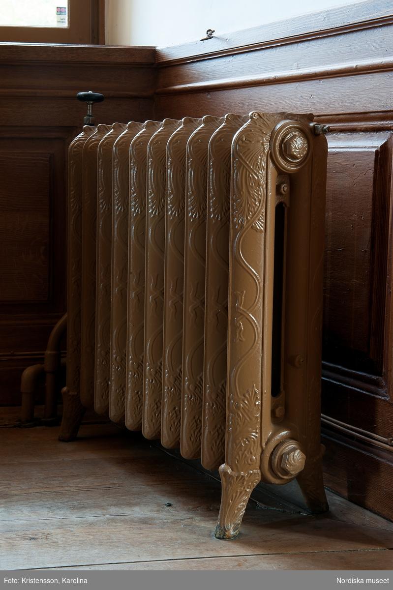
Freestanding cast-iron radiators should also be installed under or in front of a window. When installing radiators, they can extend to just under the window sill but never above it. The best place for the unit is at least 100 mm (4 in.) below the sill height. Figure 1 shows the installation of a freestanding cast-iron radiator. If air cannot continuously pass freely over the operator of the thermostatic radiator valve because of curtains or a shelf over the radiator, a thermostatic valve with a remote sensor must be used.
Cast-iron radiators are designated by the square feet of radiation they possess. Radiators are selected from manufacturers’ catalogues and specifications.
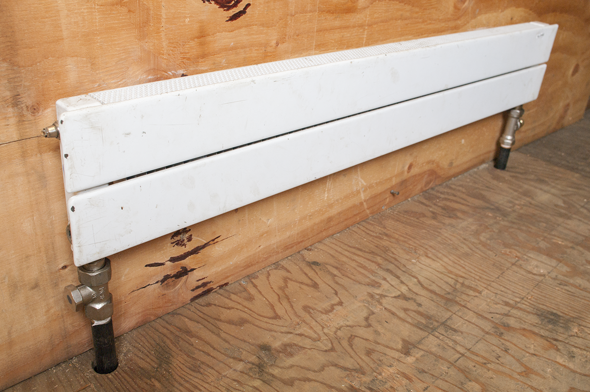
Installing Panel Radiators
Panel radiators can be installed in a wide variety of ways and be custom built for special situations. Panel radiators come in many configurations. Their selection and installation requirements can differ greatly from those of other heat transfer units, and manufacturers’ specific literature must always be consulted.
Installing Unit Heaters
Unit heaters should be selected so that they work at full capacity under design conditions and should not be selected on the basis of floor coverage. Doing so will result in having more heating output than required. In that situation, some units would operate for short periods, while others may not perform as expected, resulting in inconsistent heating.
Horizontal-flow unit heaters are usually suspended from the ceiling by two or four threaded rods, known as “redi-rod” in the industry. Always follow manufacturers’ installation guidelines in order to conform to safety and warranty considerations. Normally, unit heaters have attachment points for rods near each of the four corners. The rods should be double-nutted at each connection to ensure that vibration will not loosen the nuts. They may also need to be seismically restrained (see the information later in this section for suspended heating or cooling coils).
Unit heaters can be installed equally well on a direct return or a reverse return piping system. In either case, connect the supply water to the bottom connection on the unit heater and the return to the top connection. This allows air to be vented from the piping and the unit heater in the direction of water flow. Furthermore, counterflow piping direction is promoted for most heat exchangers, and isolation valves should be installed on both supply and return piping connections.
Locate the units in areas of the greatest heat loss, such as by doors and windows. For efficiency and ease of operation, unit heaters should be placed so that they assist each other in stirring the air. Cross-currents of air and fans that oppose one another are counterproductive. The size and discharge capacity of the unit heaters must also be taken into consideration when spacing them for efficient airflow. Consult the manufacturer’s guide for placement when designing a system.
On large buildings with open areas, unit heaters can be arranged along the perimeter without being concerned about the building’s central area, where heat loss will be minimal. Figure 3 shows a circular installation pattern (or parallel arrangement) used for a perimeter installation. The fans set up a circular flow around the room near the ceiling. Smaller air currents will circle from the front to the back of the fan, producing vertical and horizontal currents that will dampen or de-intensify the main air current.
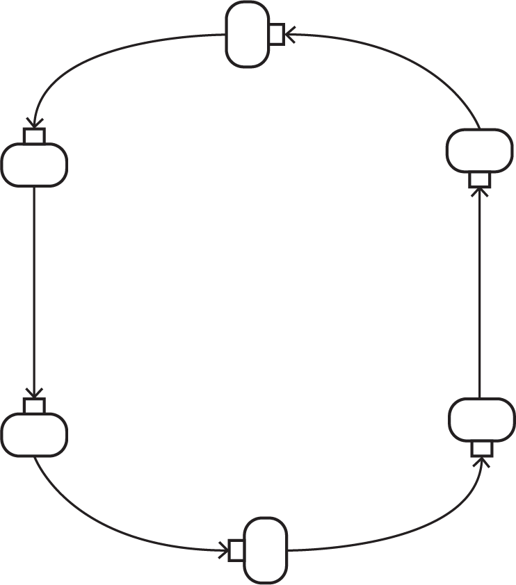
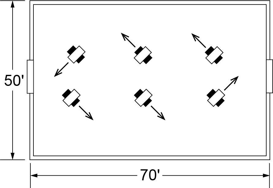
Figure 4 shows an installation pattern for a building that has high heat loss on all walls and large doors at either end. The units are installed along two lines down the middle of the building but blowing in opposite directions. Also, the units nearest the doors are positioned to blow air toward the doors.
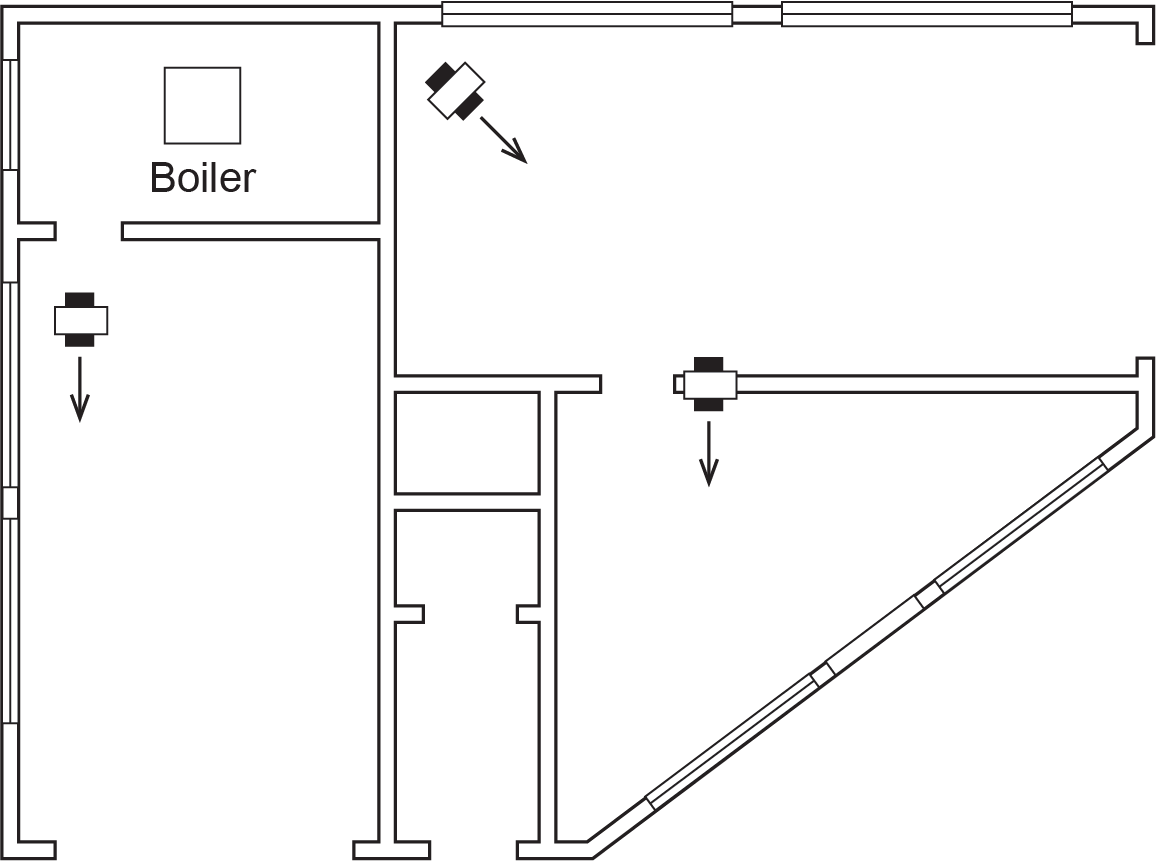
Unit heaters are well suited for locations where there is need for quick heat recovery, such as in a service station or other buildings with large and frequently opened doors. Figure 5 shows the installation of three horizontal unit heaters in a service station. In the automobile areas, the units blow air through the entire space toward the door. The office has the third unit. To prevent the air from the service areas from coming into the office, this unit should have a return air plenum or duct. A return air plenum is constructed on-site to move cooler air from the bottom of the room that the unit is installed in to the unit.
Vertical Unit Heaters
Vertical unit heaters should be installed 17 m (50 ft) apart for best performance. They should be installed high enough that dampers directing airflow cannot be tampered with once they are positioned properly.
 Self-Test B-3.2: Heat Transfer Units Installation
Complete the chapter Self-Test B-3.2 and check your answers.
If you are using a printed copy, please find Self-Test B-3.2 and Answer Key at the end of this section. If you prefer, you can scan the QR code with your digital device to go directly to the interactive Self-Test.

References
Skilled Trades BC. (2021). Book 1: Fuel gas systems, Heating and cooling Systems. Plumber apprenticeship program level 2 book 1 Harmonized. Crown Publications: King’s Printer for British Columbia.
Trades Training BC. (2021). B-3: Install hydronic transfer units. In: Plumber Apprenticeship Program: Level 2. Industry Training Authority, BC.
Media Attributions
All figures are used with permission from Skilled Trades BC (2021) unless otherwise noted.
- Figure 1 Tyresö slott, interiör, detaljer by Karolina Kristensson, via DigitaltMuseum, is used under a CC BY-NC-ND 4.0 license.
Steam cannot circulate nor can radiators emit heat until air has been vented from the system. Thermostatic air vents are installed on each radiator and at the end of each steam main. Thermostatic steam traps also act as air vents. (Section B-1.1, Section B-3.1 and Section B-3.2)
