B-2.1 Heating and Cooling Sources
The heating or cooling source can be considered the heart of the operation. This is where the heating or cooling is generated. The heat energy is transported throughout the building through a piping distribution system and finally released by heat emitters. There are many different types of heating and cooling sources, and the use of any particular type usually depends on the application. Some examples include:
- Boilers
- Conventional gas- and oil-fired boilers and condensing gas-fired boilers
- Electric resistance boilers
- Wood-fired boilers
- Solar energy heating
- Chillers
- Heat pumps
- Heat exchangers
Boilers
A boiler can be defined as a closed vessel that heats water or other fluid. This heated fluid is then distributed to the rest of the system through piping networks.
In North America, gas- and oil-fired boilers are currently used in the majority of residential and light commercial hydronic systems. Until recently, conventional (non-condensing) boilers were the most common, but as technology advances and laws are passed requiring boilers to be more efficient, condensing boilers are becoming more widely adopted.
Electrically-powered heat sources, such as electric boilers and hydronic heat pumps, and sources relying on renewable energy have not yet gained a market share comparable to fossil fuel boilers. With the increasing movement to “go green,” however, that will undoubtedly change in the future.
Boilers fall into two broad categories based on temperature and pressure:
- Low-temperature boilers: have a maximum temperature of 120°C (250°F) and a maximum pressure of 1,100 kPa (160 psig), except for cast-iron boilers, which have a maximum pressure of 207 kPa (30 psig).
- High-temperature boilers: are any boilers exceeding the above low temperatures or pressures.
Types of Boilers
The two types of boilers are hot water and steam.
Boilers can be further classified in various ways, the most common of which are:
- Heating method (fire tube or water tube)
- Material used in construction
- High mass or low mass
- Non-condensing or condensing
- High-pressure and low-pressure
Hot-Water or Steam Boilers
Boilers are pressure vessels that produce either hot water or steam. Some boilers can be used for both purposes. Hot water boilers are completely filled with water and require a circulator to move the water around the system. Steam boilers are only partially filled with water to allow steam to build. Steam boiler systems do not need pumps for circulation, but pumps are often installed to return condensed steam (condensate) to the boiler.
A boiler used to produce hot water has different accessories mounted on and around it than one used to produce steam. For instance, a steam boiler has a sight tube or “gauge glass” that visually indicates the water level within the boiler. A hot water boiler does not have these features.
Hot water boilers with over 400,000 BTU/h of input and all steam boilers, regardless of input, have a low-water cut-off mounted near the sight tube. A low-pressure steam boiler’s burner fires to maintain an operating pressure of 105 kPa (15 psig) or less, which is evident on a pressure gauge. A hot water boiler fires in response to its operating temperature, displayed on a thermometer or a tridicator.
Hot-Water Boilers
Hot-water boilers can be classified by:
- Pressure (low or high)
- Temperature (low or high)
- Materials of construction (cast iron, copper, or steel)
- Mass (low or high)
- What is carried in its tubing (fire tube or water tube)
Boilers for heating hot water may have to withstand very high pressures or heads due to the height of the water in the distribution system above them, which can often be as high as 1,120 kPa (160 psig). These would typically be steel-tube boilers, whereas cast-iron boilers normally operate at pressures not exceeding 210 kPa (30 psig) due to their brittleness and large surface area in contact with the pressurized water.
High-temperature water, defined as exceeding 121°C (250°F), is not normally used for hot-water heating because it requires greater pressure to maintain its liquid state. Hot water boilers normally operate at average temperatures of 82°C (180°F) to stay below water’s atmospheric boiling point. Hot-water boilers are known as “low thermal mass” if they contain very little water and “high thermal mass” if they have a large water content.
Hot-water boilers use an aquastat to control the burner. An aquastat is a switch that reacts to the temperature of water, which opens to de-energize the burner circuit when the water reaches its operating temperature. The system pressure is set and maintained by a pressure reducing valve on the boiler’s inlet water makeup, and the pressure setting depends on the height of the system. This section will discuss boiler construction later on.
Steam Boilers
In steam boilers, water must boil to produce steam. Steam boilers may be made of cast iron or steel tube. Steel-tube boilers may be fire-tube or water-tube.
Steam boilers are categorized as low-pressure or high-pressure. The production of steam increases pressure. The American Society of Mechanical Engineers’s (ASME) regulations require that steam for heating does not exceed 105 kPa (15 psig) of pressure. In fact, most steam systems operate between 0.5 and 2 psig of steam pressure. Therefore, all steam boilers for heating systems are low-pressure boilers. Water boils at 121°C (250°F) at 105 kPa (15 psig) of pressure. To keep steam boilers at or below the specified maximum pressure, a pressure switch, rather than an aquastat, is used to control the boiler burner.
Heating Methods
Boilers heat water by using one of three methods:
- Fire-tube boiler: heated flue gases travel through tubes that are surrounded by the water in the boiler.
- Water-tube boiler: water travels through tubes that are surrounded by the hot flue gases within the fire chamber.
- Cast-iron sectional boiler: water is contained in tanks called sections, with hot flue gases passing around the sections.
Fire-Tube Boilers
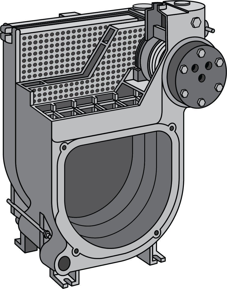
Fire-tube boilers (Figure 1) are made of steel tube and can produce hot water and steam equally well. They can be low-pressure or high-pressure, but high-pressure fire-tube boilers are rare.
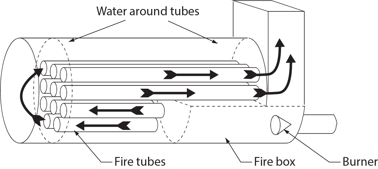
A fire-tube boiler consists of a water chamber that contains a number of tubes, called fire-tubes, that carry heated flue gases. Fire-tubes form horizontal passages through the water chamber and are vented into the atmosphere. The arrows in Figure 1 show the direction of movement of the heated flue gases through the fire tubes.
The firebox contains a burner and a flame. The firebox and the lowest level of fire tubes together are called the fire chamber. Flame and hot gases from the firebox travel through the fire tubes and heat the surrounding water by conduction. Due to the large surface area of tube in contact with the water, a high percentage of heat is transferred by conduction through the tube walls to the water.
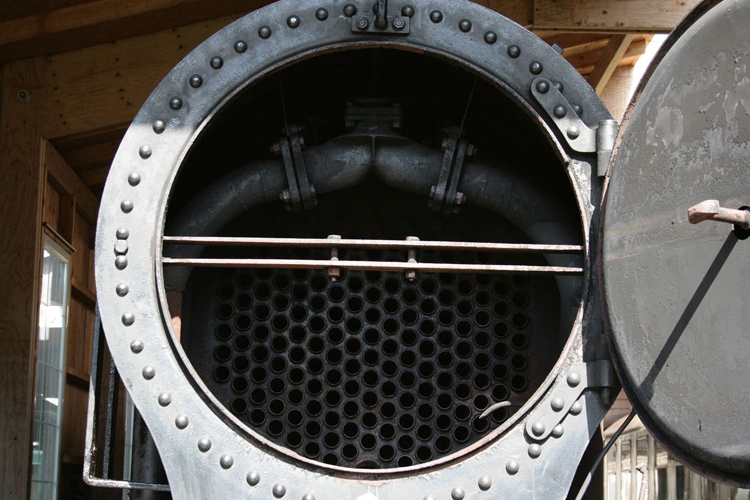
Fire tubes contain baffles to guide the hot flue gases through the fire tubes and help spread the heat evenly throughout the tubes. Some of these baffles are visible when opening the access door at the end of the boiler to inspect the boiler’s condition or remove soot (Figure 2).
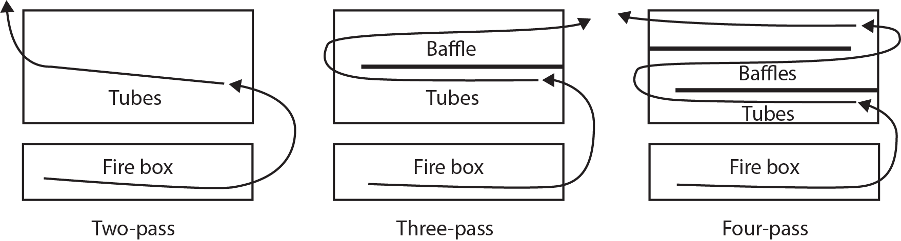
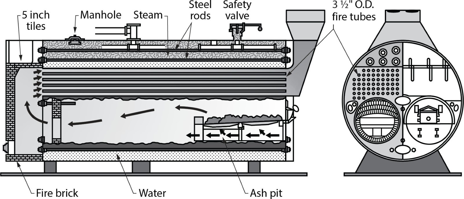
The path that the heated flue gases take through the length of the boiler depends on the layout of the fire tubes. Fire-tube boilers are identified by the number of “passes” that the heated gases make. For example, a three-pass boiler (Figure 3) has the heated flue gases passing through the firebox once and through the water chamber twice. Two-, three-, and four-pass boilers are common. The “Scotch,” or “Scotch marine,” boiler (Figure 4) is a large, two-pass fire-tube boiler.
Water-Tube Boilers
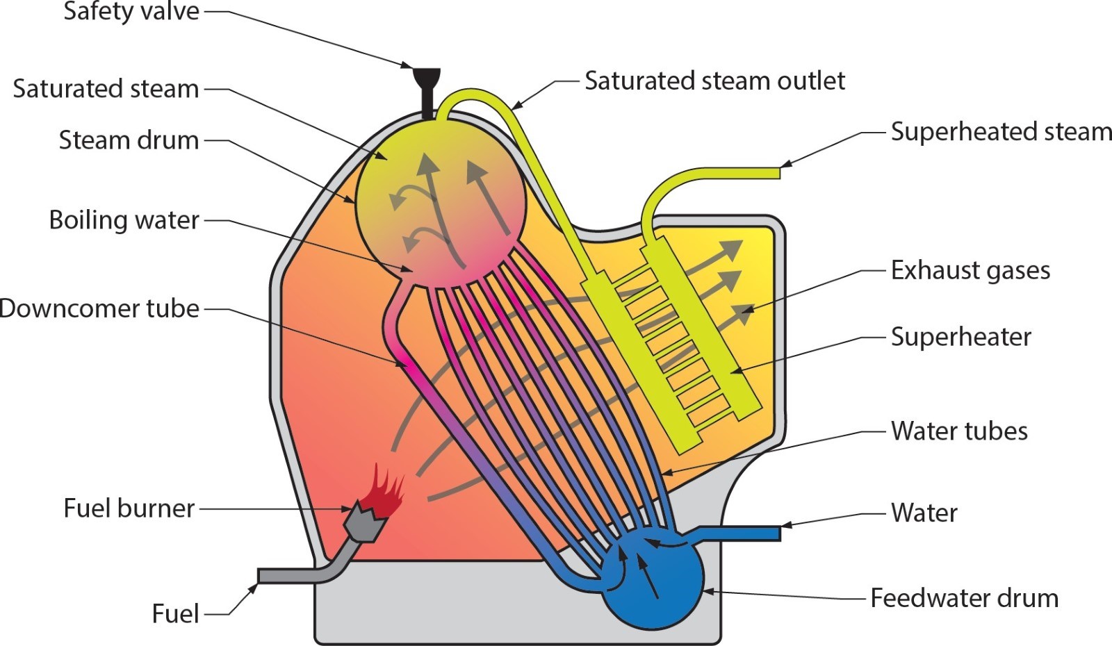
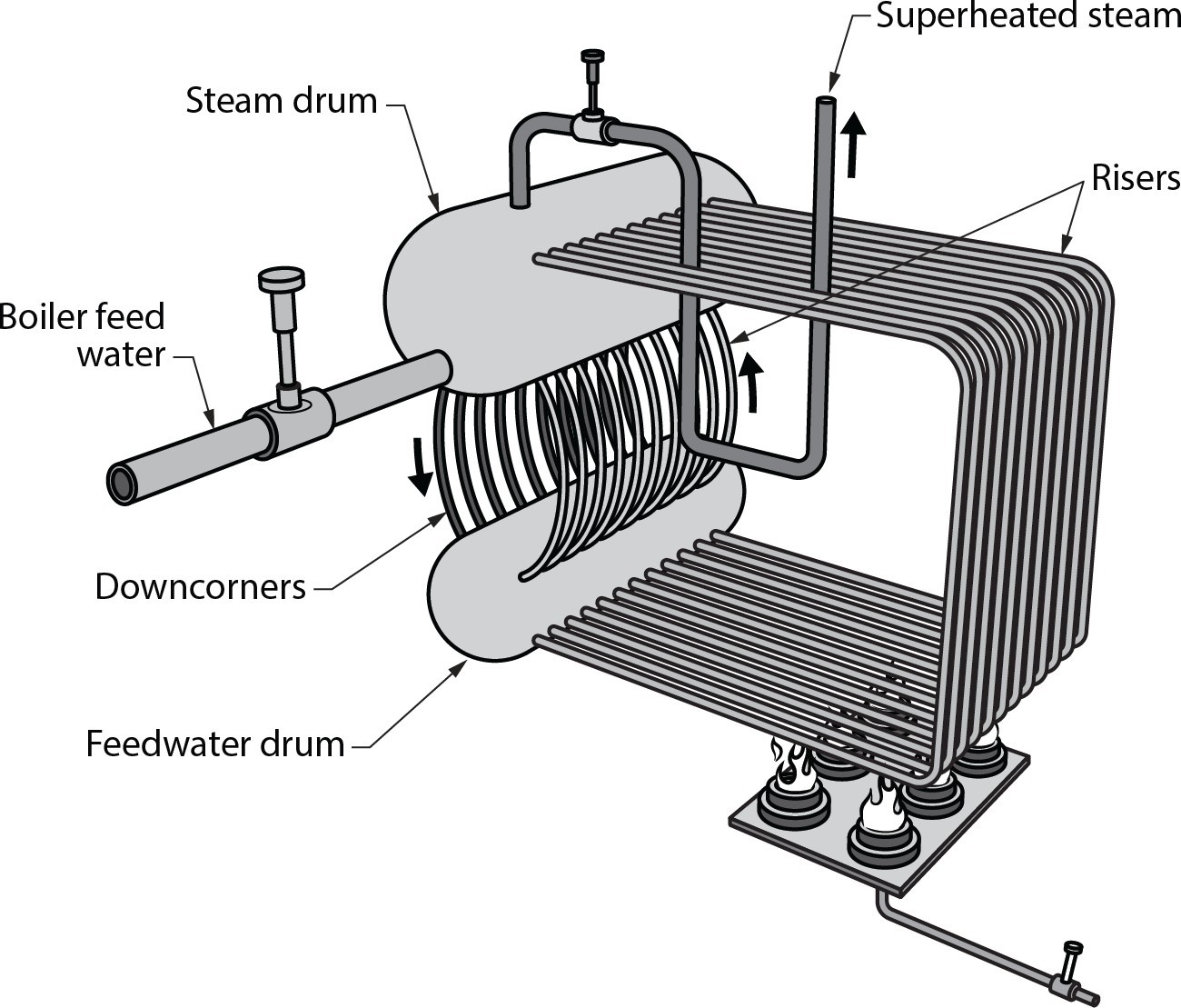
Steel water-tube boilers (Figure 5) can produce both hot water and steam and can be low-pressure or high-pressure. A steel water-tube steam boiler consists of a system of nearly vertical pipe exposed to heated flue gases in a fire chamber. The water tubes are connected to a cylindrical steam drum at the top and a feedwater drum at the bottom.
In large-scale applications, water-tube boilers are considered safer than fire-tube boilers. If a single water tube should leak during the boiler’s operation, the only water immediately affected is from that single water tube. If a fire-tube boiler should leak during operation, the entire water mass will be affected, sometimes with cataclysmic results.
Steel water-tube boilers are well suited for producing steam in great volumes and at high pressures and are normally used for power or process applications. Pipe arrangements inside many small low-pressure water and steam boilers are quite similar to the internal configurations of water-tube boilers. Water-tube boilers may be constructed of steel or copper tube. Copper water-tube boilers typically have fins attached to them to greatly increase their surface area, which increases heat transfer. These boilers can also be used to directly heat domestic water because of their high corrosion resistance.
Cast-Iron Sectional Boilers
Cast-iron boilers can be used to produce hot water or steam and are classed as low-pressure boilers. Cast-iron boilers for hot water heating can be identified by the letter “H” on their rating plate.
A cast-iron boiler has a number of chambers, known as sections, that fit together in a sandwich pattern (Figure 7). Each section consists of a grid of water tubes. Small fins and a header on each end of the tubes allow the water to be routed from one section to the next. As the hot exhaust from the burner passes through the grids, it heats the water in the tubes.
Push nipples connect the sections together and seal the water passages between them. The sections are held together with tie rods that pull the sections together. This makes it possible to replace cracked sections without needing to replace the entire boiler. This sectional design also enables the manufacturer to supply a range of boiler sizes (outputs) for a particular model by varying the number of sections.
The amount of metal in them makes cast-iron boilers very heavy. Even a small residential boiler can weigh 130 kg to 180 kg (300 lb to 400 lb), and such boilers typically contain 40 L to 64 L (10 gal to 16 gal) of water. Cast-iron boilers are classified as high mass boilers due to their large water volume.
Boiler Materials
Boilers can be made from a variety of metals, but the three most common are steel, copper, and cast iron. Water-tube boilers are either copper water-tube or steel water-tube. Fire-tube boilers are generally steel tube, while cast iron is only used for sectional boilers.
Stainless steel’s resistance to corrosion makes it ideal for use in condensing boilers. It was rarely used as a construction material for non-condensing boilers due to its cost, but with the trend these days leaning toward high-efficiency condensing boilers, its use is rapidly increasing.
High Thermal Mass Boiler vs. Low Thermal Mass Boiler
Traditional large boilers are classified as high mass boilers. They are made from heavy steel or cast iron and outfitted with large-diameter pipes that hold large volumes of water. These two facts combined mean that high mass boilers are large, weigh a lot, and take a long time to heat up; however, they also hold a lot of heat and retain it for a long period of time.
By comparison, low mass boilers hold far less water. They are generally constructed of steel, copper, or stainless steel. The low volume of water means that low mass boilers can react more quickly to different situations and are generally more efficient than high mass boilers. Another point to be aware of is that water must always be flowing through a low mass boiler while the burner is firing. If water is not flowing, the boiler will quickly overshoot its operating and high-limit setpoints, and the water within the tubing will boil, causing noise and stress on the boiler and much anxiety for people around it.
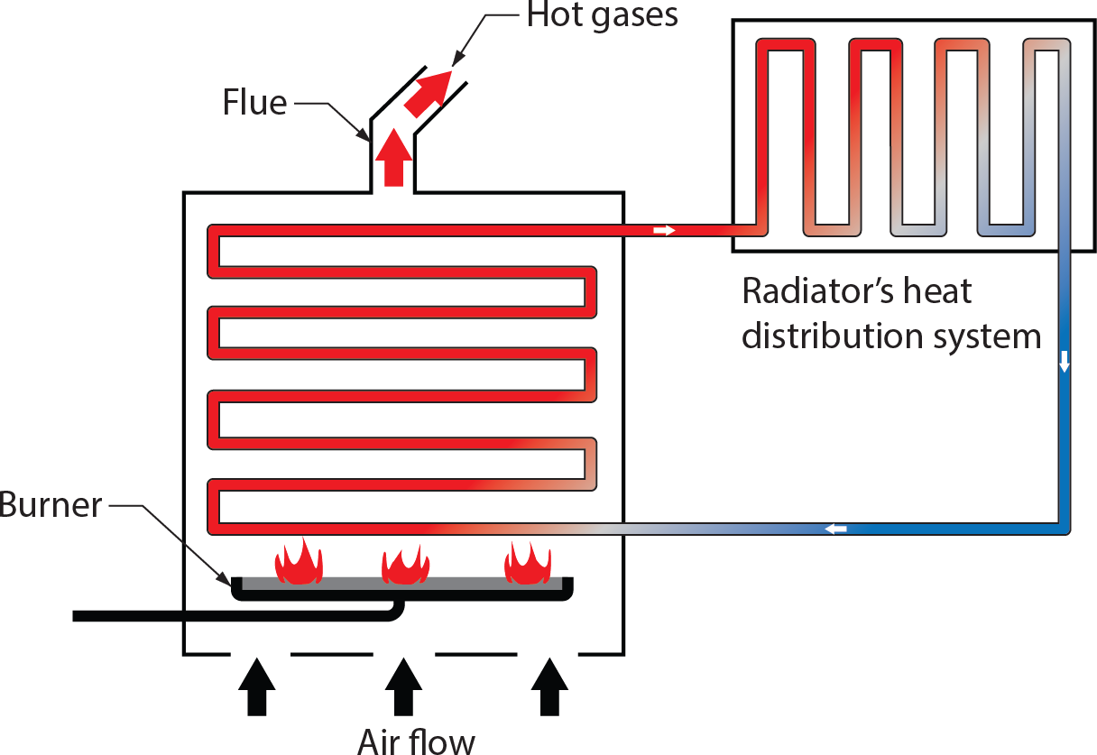
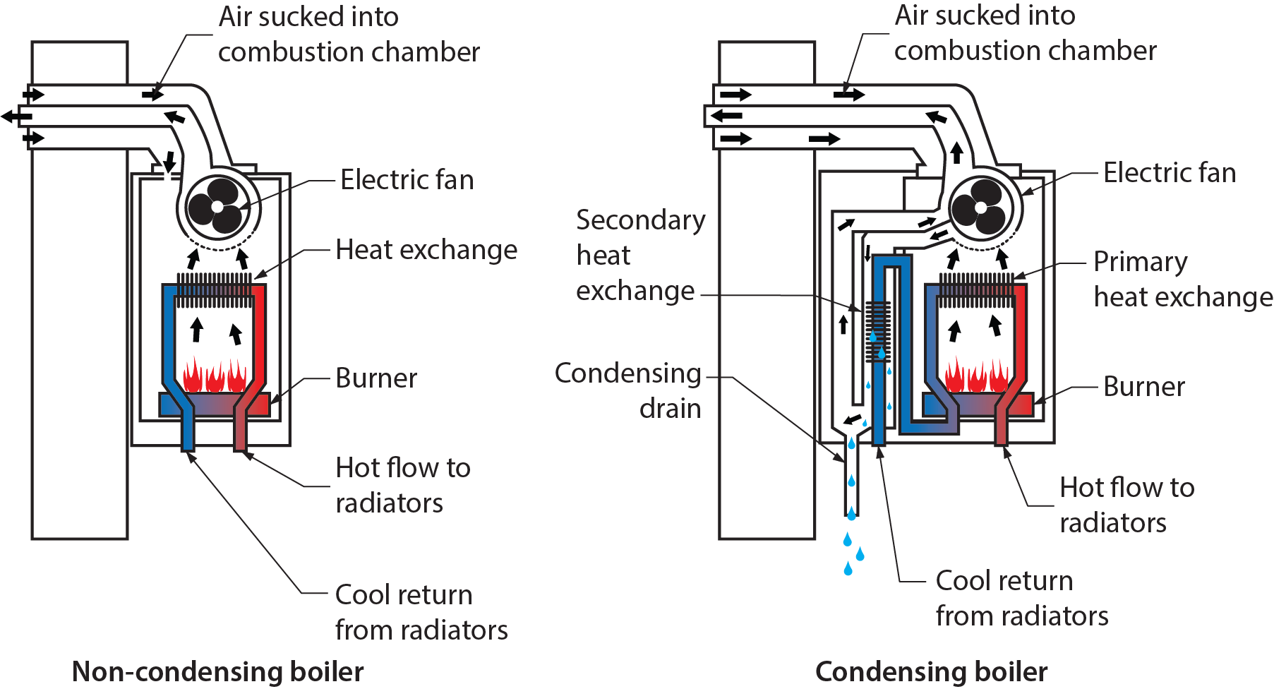
Non-Condensing Boilers
Non-condensing (conventional) boilers (Figure 8) have traditionally been the mainstay of the hydronics industry, but this has changed in the last few decades. Traditional boilers typically heat water to a temperature between 77°C and 88°C (170°F to 190°F). In a properly designed heat distribution system, the water temperature drops approximately 6.5°C (20°F) before the water returns to the boiler.
A non-condensing boiler is made of materials that cannot maintain their integrity if the return water temperature is any lower than 60°C (140°F). Water returned to a boiler below this temperature will cause the vaporized water in the flue gases to condense. Because non-condensing boilers are not equipped to withstand the condensate, which is typically acidic, the heat exchanger and other parts of the boiler will start to deteriorate.
The return water temperature is what distinguishes a non-condensing boiler from a condensing boiler.
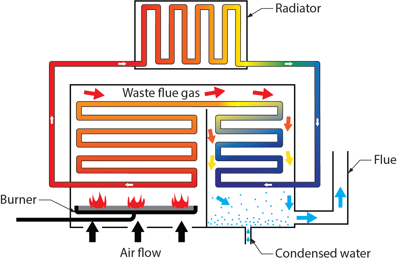
Condensing Boilers
Condensing boilers remove more heat from the flue gases than non-condensing boilers. This means the return water temperature going into the boiler is below 60°C (140°F).
Today’s condensing boilers are designed to function with low return water temperatures that condense within the combustion chamber of the boiler. The condensate is put through an acid neutralizer before being drained into the building’s sanitary drainage system (Figure 10). The increase in efficiency is offset by the need to construct the boiler with corrosion-resistant material, such as stainless steel and titanium alloys. Nearly all modern condensing boilers can modulate their heat output to better match the system demand. They do this by turning down the gas input as much as [latex]\tfrac{1}{5}[/latex] (20%) of their rated maximum input. This amount of modulation would be called a five to one turndown ratio. These boilers are often referred to as ModCon boilers.
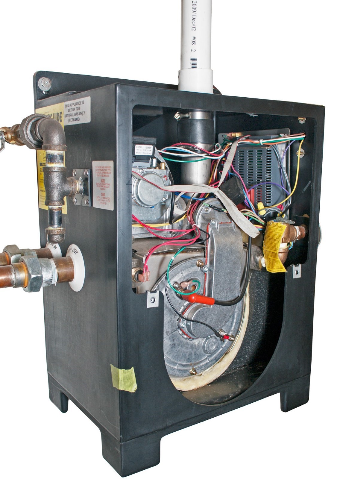
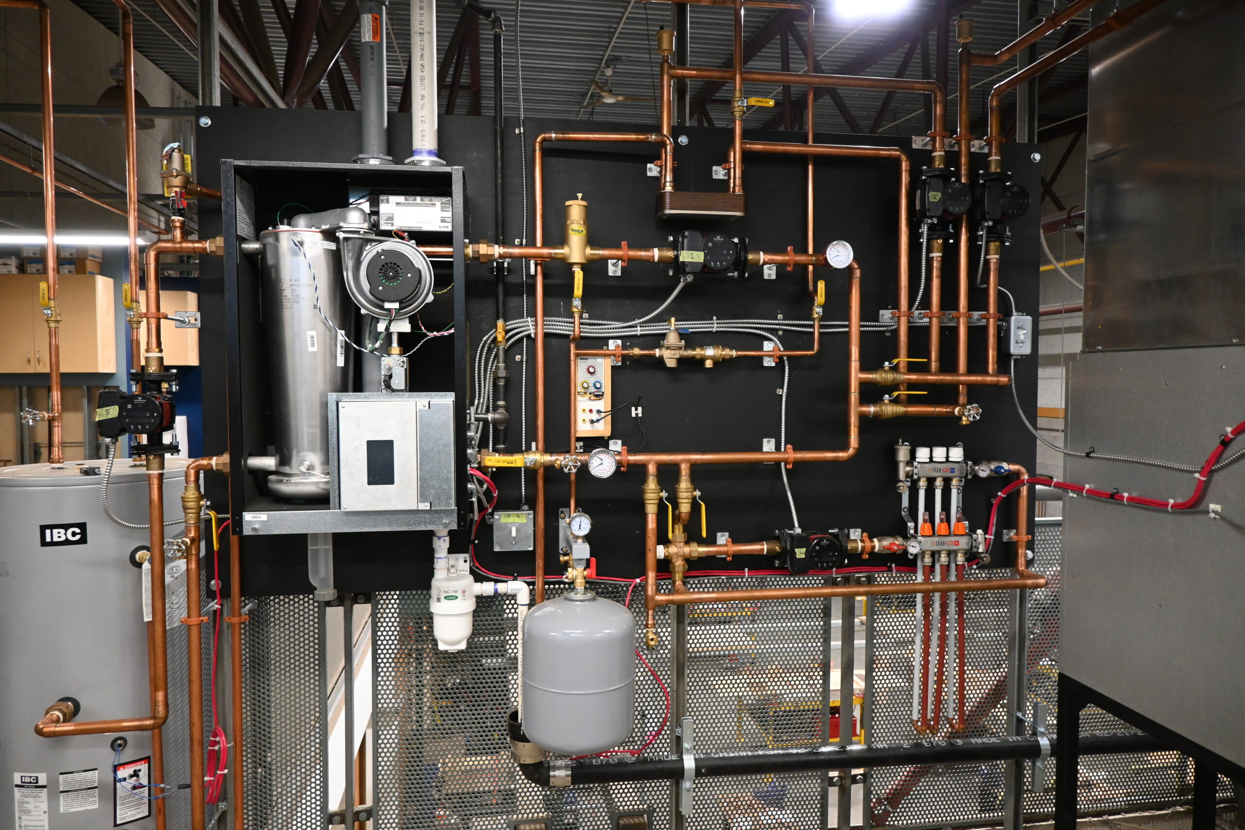
Packaged Boilers
In the past, boilers and their associated components were obtained piece by piece, assembled and tested at the job site. These were originally cast-iron sectional boilers that were often massive in size, very heavy once assembled, and unable to fit through conventional room openings. Industrial cast-iron boilers are still shipped and installed in this manner. When the building boom of the post-war 1940s hit North America, hot water heating took off in a big way. Boiler manufacturers, looking to sell more product, realized that by installing more components onto the boilers at the factory, more installers would buy them, and the result was “packaged” boilers.
Since then, most boilers for residential and small commercial use have been fully assembled and tested at the factory. Packaged boilers can be made of cast iron, copper tube, steel tube, or stainless steel. They have an insulated cover (jacket) and normally come with the minimum-size circulator and electrical controls required to operate it already attached and wired.
Because the boiler is assembled, tested, and adjusted at the factory, the only onsite connections required are:
- Water makeup
- External electrical controls (e.g., thermostats, additional transformers, and zone valves)
- Supply and return piping mains
- Fuel supply
- Venting system
- Air supply (if applicable)
Note in Figures 11a and 11b that the circulator is likely not mounted in the best position for system performance. Mounting the circulator on the return of the boiler took care of a couple of problems present at the time. One was that the pump seals at that time could not take the high temperatures of the boiler supply piping, so it was mounted where the water would be the coolest. As well, the packaging for the boiler did not have to be as tall if the pump was mounted low on the boiler return. A later section will cover these points, but common practice is to remove the circulator from a packaged boiler and install it on the boiler supply piping downstream of the expansion tank connection.
Boiler Ratings
All boilers must be marked with important information for installation and operation purposes. This information is found on what is known as a rating plate. It must be indelible and able to remain attached to the boiler throughout its operational life.
Boiler ratings consist of the boiler’s gross output and input, in either BTU/h or kW. Input is the amount of energy the boiler consumes to produce heat. Output is the amount of energy actually transferred to the medium being heated (water, heating fluid, glycol, etc.). The ratio of output-to-input energy represents the efficiency of the boiler. All boilers that burn fossil fuels have a loss of efficiency because of their inability to transfer all of the heat produced into the water. Some of it will always be lost through the venting system into the atmosphere. This is called waste heat or waste energy.
Efficiency is a percentage that is calculated as follows:
[latex]\color{blue}{(\text{output}\div \text{input})\times100}[/latex]
For example, a house might have a boiler that has an input rating of 59 kW (200,000 BTU/h) and a gross output rating of 47 kW (160,000 BTU/h). Therefore, the efficiency of this boiler is:
[latex]\color{blue}{(47\text{ kW}\div 59\text{ kW})\times 100=79.7\%}[/latex]
or
[latex]\color{blue}{(160\,000\div 200\,000)\times 100 = 79.7\%}[/latex]
In economic terms, one could say that efficiency is an expression of how much of a dollar spent on fuel actually goes into heating the building and how much ends up as waste heat.
Efficiency can be estimated in numerous ways. The accepted benchmark for efficiencies in heating equipment is called annual fuel utilization efficiency (AFUE). This method tracks the appliance’s use over a year and is the most realistic expression used. Another expression of appliance efficiency is steady state efficiency, where an appliance operates for eight hours continuously while heat-transfer readings are taken. Because most appliances do not normally operate this way, steady state efficiencies are not seen as representative of the actual operation of an appliance.
Until the late 1980s, most boilers operated at efficiencies of a little less than 80%. The addition of vent dampers, which close off the boiler from its flue to prevent heat being lost up the vent when the burner is not firing, helped retain much of the heat produced during the run cycle and gained some points of efficiency. Modern conventional boilers now exceed 80% efficiency (known as “mid-efficiency”), and condensing boilers can exceed 90% efficiency (known as “high-efficiency”) by passing the hot flue gases through a second heat exchanger. Therefore, the amount of heat wasted is greatly reduced. Because the flue gases have now lost their heat and cannot float up through the venting system on their own, they must be forced out with a fan.
The current edition of the BC Building Code, which reflects the National Building Code, publishes the minimum acceptable AFUE for new installations of gas-fired boilers not over 88 kW (300,000 BTU/h) of input to be ≥90%. This would encompass the range of almost all residential boilers. New installations of gas-fired boilers that exceed 88 kW (300,000 BTU/h) input must have a minimum thermal efficiency of ≥83%.
Solar Thermal Hydronic Heating
Solar thermal technologies use the free, renewable, non-polluting power of the sun to heat water and air in commercial and residential buildings. Panels called solar collectors use the infra-red rays from the sun to heat either water or a heat-transfer fluid circulating within them. The target for the heat from the collectors could be the domestic hot water system or for assisting heat pumps used in ground source heating systems. Systems can be classed as active or passive and either direct or indirect.
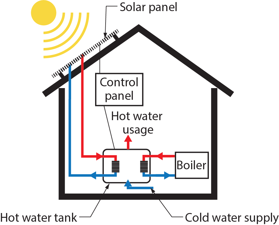
Active Solar Watering Heating Systems
Active systems use electric pumps, valves, and controllers to circulate water or other heat-transfer fluids through the collectors. There are three types of active systems:
- Direct systems: use pumps to circulate water through the collectors. These systems are appropriate in areas that do not freeze for long periods and do not have hard or acidic water. Systems installed in hard or acidic water conditions may not survive the “payback period” if care is not taken to address water chemistry. In off-grid situations where solar energy may be the only option, water chemistry must be considered.
- Indirect/closed-loop systems: pump heat-transfer fluids, such as a mixture of glycol and water, through collectors. Heat exchangers then transfer the heat from the fluid to the water within the heating system. These systems are used in climates subject to freezing.
- Drainback systems: are direct systems that use pumps to circulate water through the collectors, then drain themselves automatically to prevent freezing. Because the water in the collector loop drains into a reservoir tank when the pumps stop, this is still a good system for colder climates and does not require antifreeze and a heat exchanger.
Solar Collectors
Solar thermal collectors are the key component of active solar watering systems and are designed to meet the specific temperature requirements and climate conditions for different end-uses. There are several types of solar collectors:
- Flat-plate collectors
- Evacuated-tube collectors
- Concentrating collectors
- Transpired-air collectors
Residential and commercial building applications that require temperatures below 93°C (200°F) typically use flat-plate (or transpired-air collectors), whereas those requiring temperatures greater than 93°C use evacuated-tube or concentrating collectors.
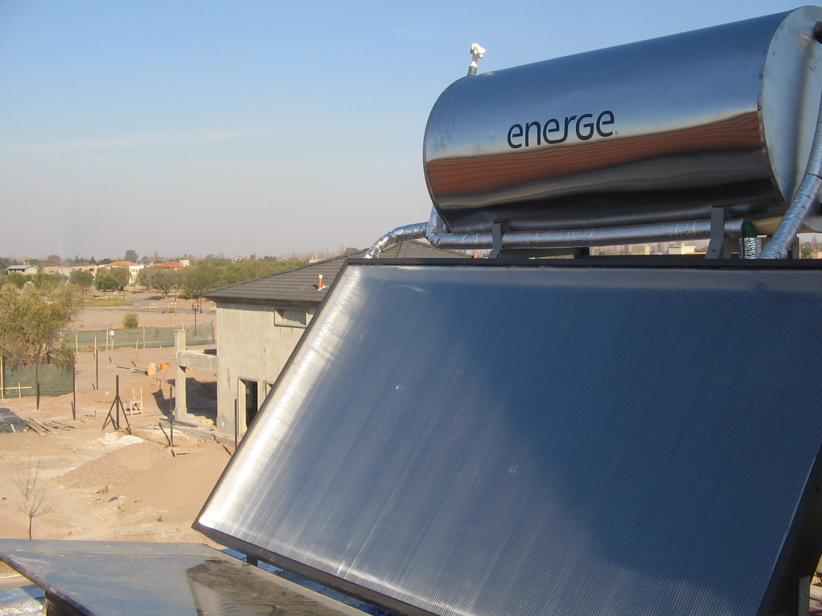
Flat-Plate Collectors
Flat-plate collectors (Figure 14) are the most common collectors for residential water heating and space heating installations. A typical flat-plate collector is an insulated metal box with a glass or plastic cover (called the glazing) and a dark-coloured absorber plate. These collectors heat either liquid or air at temperatures less than 82°C (180°F).
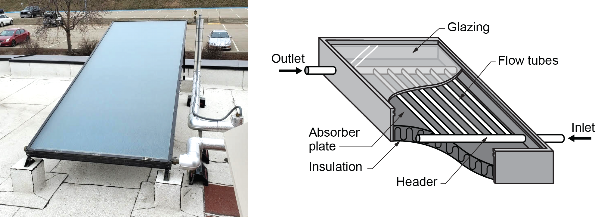
Liquid flat-plate collectors heat liquid as it flows through tubes in or adjacent to the absorber plate. The simplest liquid systems use potable household water, which is heated as it passes directly through the collector, then flows to the house.
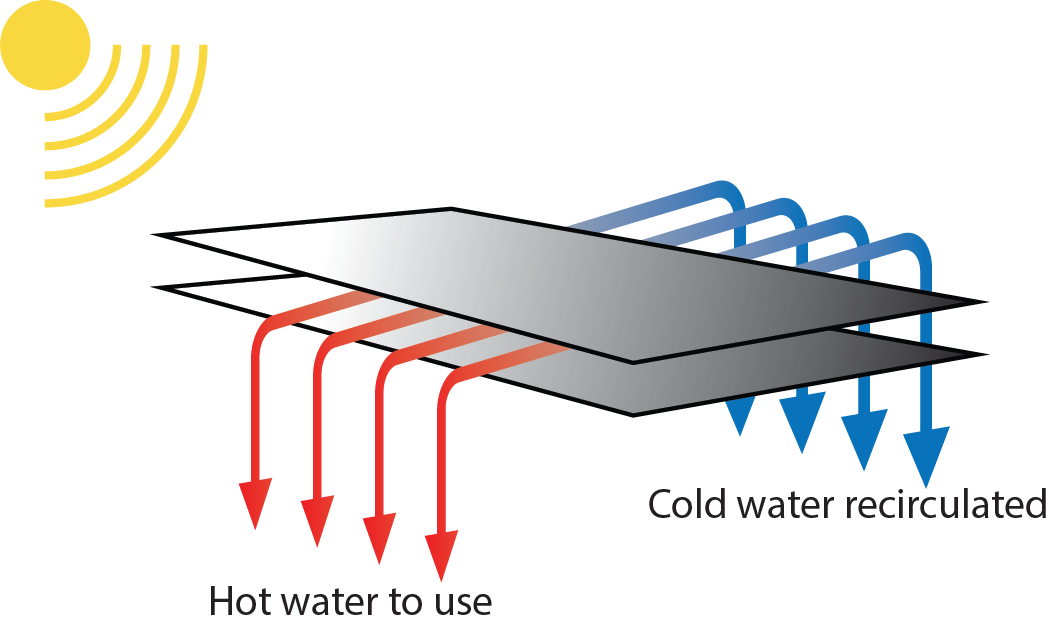
Swimming pool heating systems (Figure 15) use liquid flat-plate collector technology. The pool’s existing filtration system pumps water through the solar collectors, and the collected heat is transferred into the pool. Because solar pool collectors operate just slightly warmer than the surrounding air temperature, these systems typically use inexpensive, unglazed, low-temperature collectors made from specially formulated plastic materials.
Glazed (glass-covered) solar collectors are usually not used in pool heating applications, except for indoor pools, hot tubs, and spas in colder climates. In some cases, unglazed copper or copper-aluminum solar collectors are used.
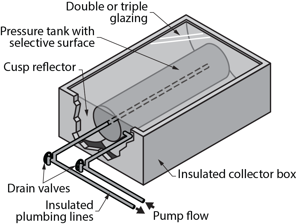
Integral collector storage (ICS) collectors (also called batch or breadbox water heaters, Figure 16) combine the collector and storage tank into an insulated box with a glazed side facing the sun. The sun shining into the collector strikes the storage tank, directly heating the water inside it. In colder climates, the use of double glazing and selective surfaces prevents freeze damage to the collector. In even mildly cold climates, insulation needs to be installed and maintained to prevent supply and return pipes from freezing.
Evacuated-Tube Collectors
Evacuated-tube collectors (Figure 17) are typically more efficient at higher temperatures than flat-plate collectors. In an evacuated-tube collector, sunlight enters through the outer glass tube and strikes the absorber, where the energy is converted to heat. The heat is transferred to the liquid flowing through the absorber. The collector consists of rows of parallel transparent glass tubes, each of which contains an absorber covered with a selective coating. The absorber typically has a fin-tube design (fins increase the absorber surface and heat-transfer rate), although cylindrical absorbers can also be used.
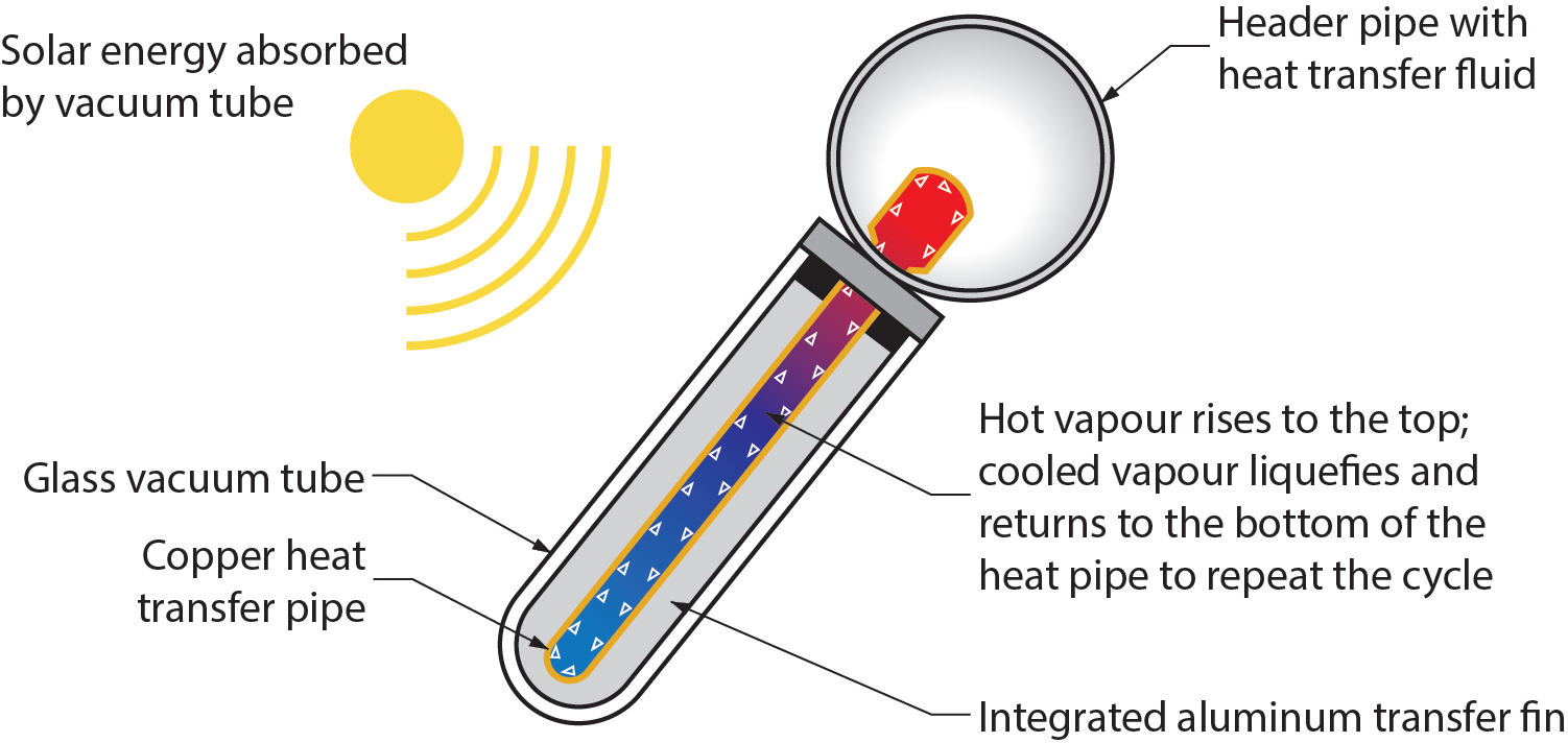
When evacuated tubes are manufactured, air is evacuated from the space between the two tubes, forming a vacuum. The vacuum is important because the liquid within it boils and the vapour rises to the top of the tube, where it contacts the metal tip of the tube. The tip is pushed into the collector manifold, where it transfers its heat by conduction to the fluid flowing through the manifold.
Evacuated tubes can be replaced simply by pulling them out of the manifold. The two heating mediums never mix together so the system does not need to be drained to replace a damaged tube. Heat losses are greatly minimized because there is no air to convect or conduct heat away, so evacuated-tube collectors are efficient at higher temperatures and perform well in both direct and diffuse (cloudy day) solar radiation.
Evacuated-tube collectors are more appropriate for most commercial and industrial applications because they can achieve extremely high temperatures of 77°C to 177°C (170°F to 350°F). However, evacuated-tube collectors are more expensive and produce higher temperatures than needed in residential settings, so most residential systems use flat-plate collectors. Because the glass vacuum tube emits no heat, snow is able to accumulate on them, which insulates the vacuum tube from the solar energy. This can be a problem in low temperature regions. In such cases, some commercial and institutional buildings have integrated liquid flat-plate collectors and evacuated tube collectors in the same system.
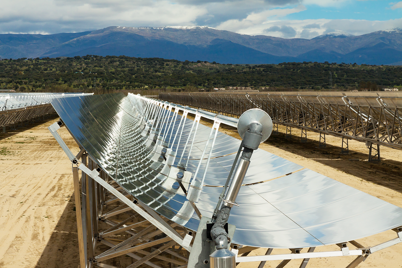
Concentrating Collectors
Concentrating collectors (Figure 18) use curved mirrors to concentrate sunlight on an absorber, called a receiver, at up to 60 times the sun’s normal intensity. These high-temperature systems are used primarily in commercial and industrial applications.
Passive Solar Water Heating Systems
Systems that move water or heat-transfer fluid without pumps are called passive systems. There are two types of passive systems:
- Integral collector storage (ICS): consists of one or more storage tanks placed in an insulated box with a glazed side facing the sun (mentioned above, Figure 16). During the winter, the connecting piping must be protected from freezing or be drained.
- Thermosiphon systems: (Figure 19) rely on convection created between the fluids in the tank and in the collector. The fluid in the collector becomes less dense and rises into the tank above, while the denser fluid in the bottom of the tank falls through piping into the bottom of the collector to be reheated. The fluid to be heated is circulated through a separate path within the tank (heat exchanger), where it absorbs the heat created and returns to the building for use.
Commercial Cooling Equipment
Cooling equipment used in air conditioning equipment or process industries relies on the refrigeration cycle. Vapour-compression mechanical refrigeration systems, as they are known, may differ in size and appearance of their components, but they all operate in the same way. Compressors, condensers, expansion devices, evaporators, and refrigerants are all used in the process of cooling.
Chillers
Chillers are the core of commercial cooling systems. It is important to remember that the refrigerant and the cooling medium (chilled water) never mix in a cooling system; heat transfer occurs solely through conduction in heat exchangers. The next section first looks at what happens in the chilled water piping and then examines the operation of the refrigeration system within a chiller.
The Refrigeration System
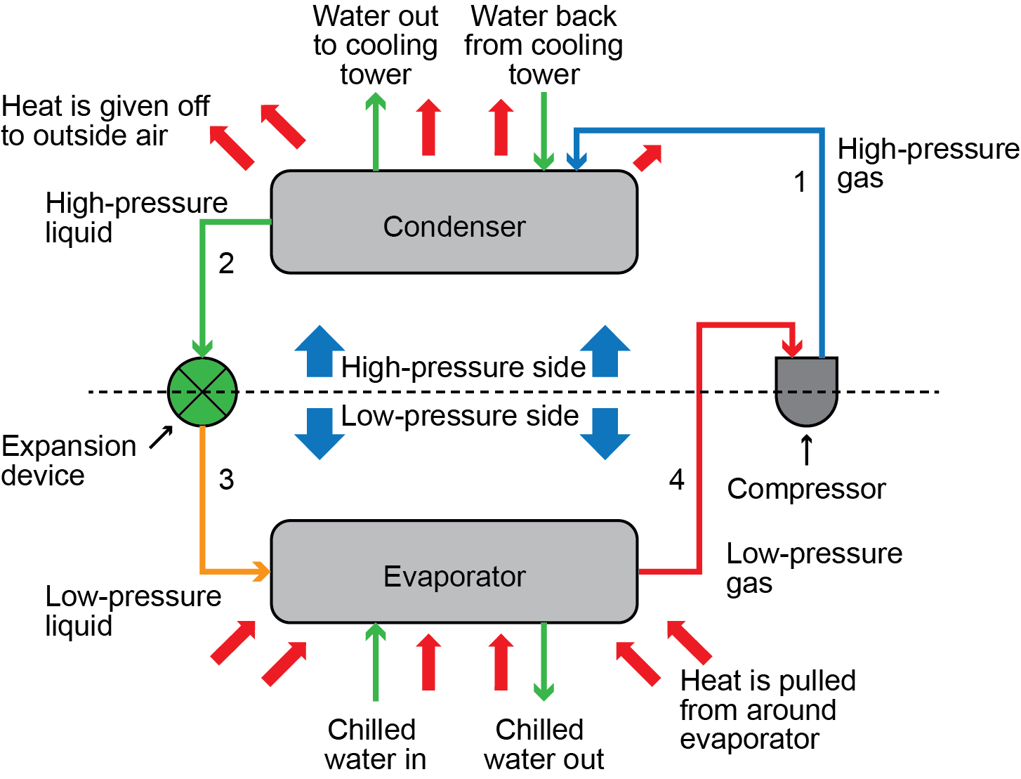
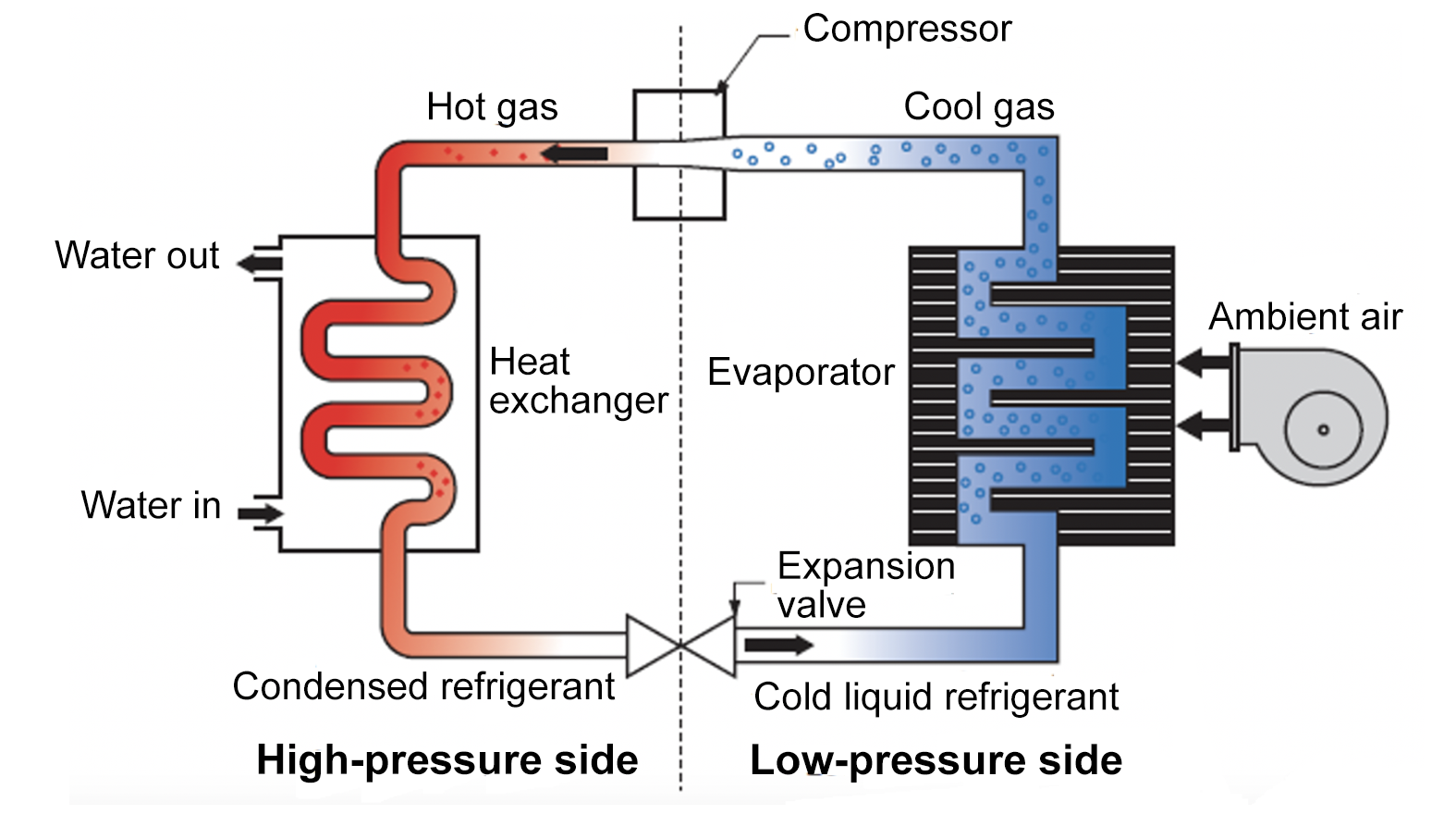
The refrigeration system in a chiller is similar to that in a refrigerator, with the main exception being its size. The actual cooling of the chilled water is done by the evaporator. After cooling the chilled water in the evaporator, the low-temperature, low-pressure refrigerant is pulled into a compressor, where both the pressure and temperature are increased (Figure 20).
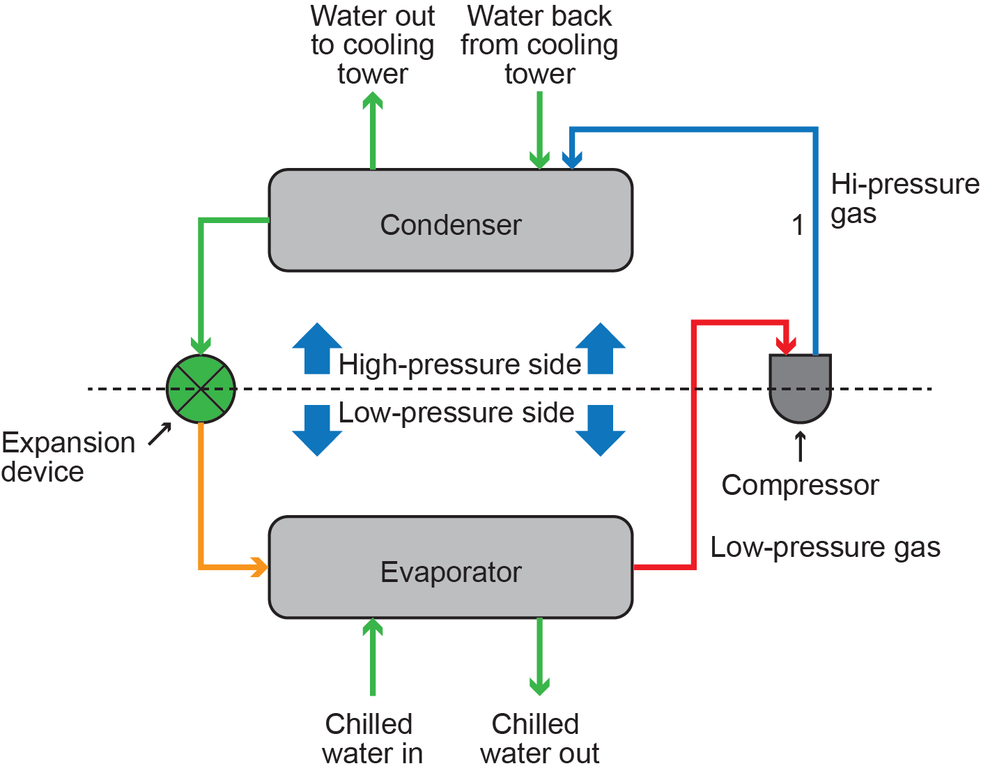
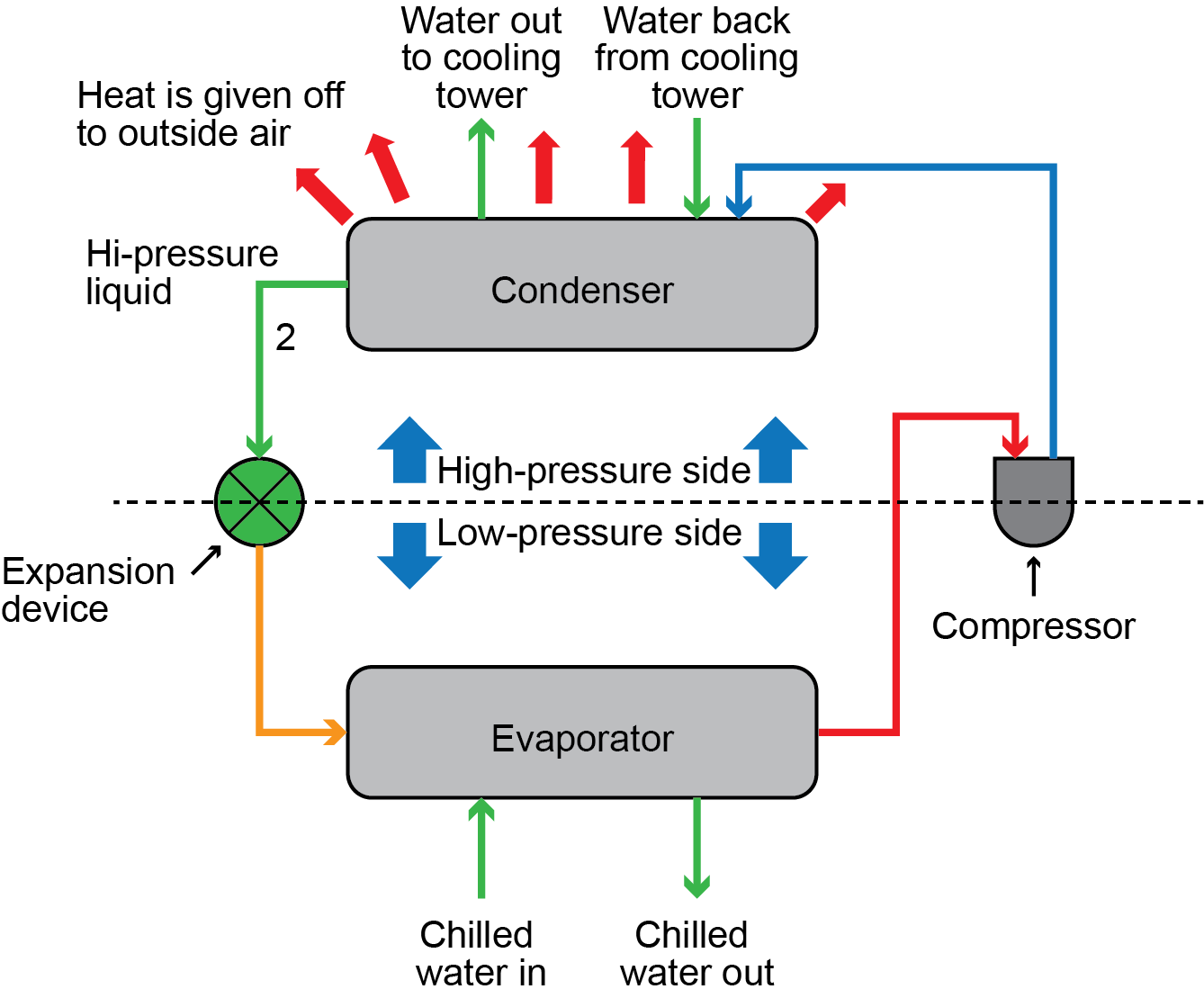
The refrigerant is pushed into the condenser, where enough heat is removed through the condenser’s coils so that the vapour condenses back into liquid form (Figure 21).
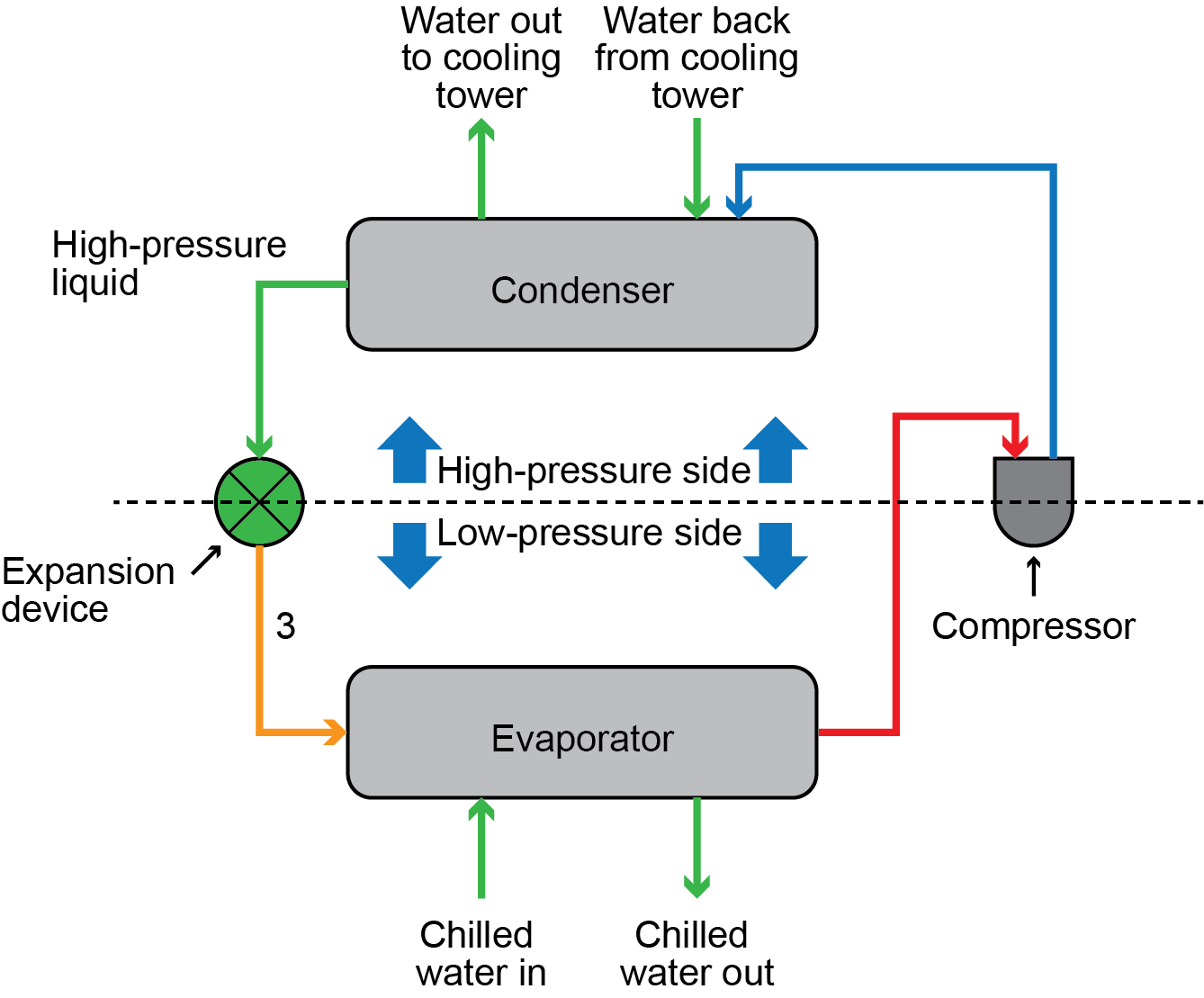
The high-pressure liquid refrigerant is then pushed through an expansion valve, which drops the pressure of the refrigerant on its way to the evaporator (Figure 22).
Once in the evaporator, the heat from the chilled water return is absorbed into the low pressure liquid refrigerant, boiling it, which, in turn, cools the chilled water (Figure 23). Then, the process repeats.
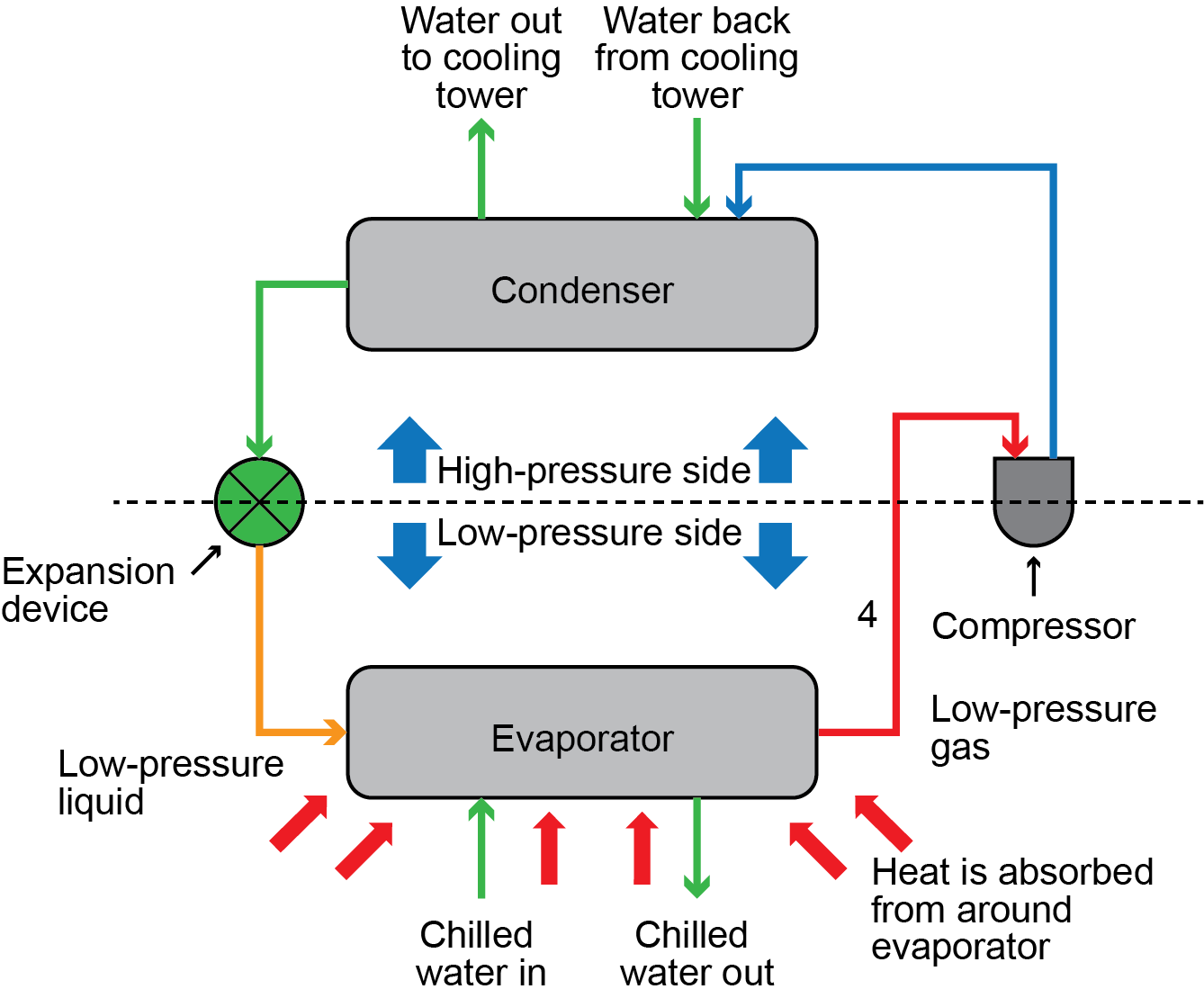
Figure 24 shows the entire process in one view.
Chilled Water System
The chilled water supply and return piping is a closed loop, which means that the system has no openings. The chilled water supply becomes the chilled water return after the water passes through the cooling coils, and the chilled water return becomes the chilled water supply after the water passes through the chiller.
Cold (or chilled) water is supplied to cooling coils in ductwork by a “chilled water supply” pipe from the chiller. In the ductwork, air is blown through a cooling coil, with the chilled water flowing through it. Heat from the air is transferred to the cooling coils and, in doing so, the chilled water lines absorb the heat from the air. The now-warmed chilled water is returned to the chiller through the “chilled water return” piping to be recooled.
At the chiller, the return water from the ductwork coils enters the evaporator section, which is a heat exchanger. The heat from the return water, in contact with the walls of the evaporator, is transferred to the refrigerant and causes it to boil. Because the heat in the water has been used to boil the refrigerant in the evaporator, the water temperature drops back to approximately 10°C (50°F). The now-chilled water is pumped back out into the system to the cooling coils, and the process is repeated until the call for cooling is satisfied.
The condenser section of a chiller can be either air-cooled or water-cooled.
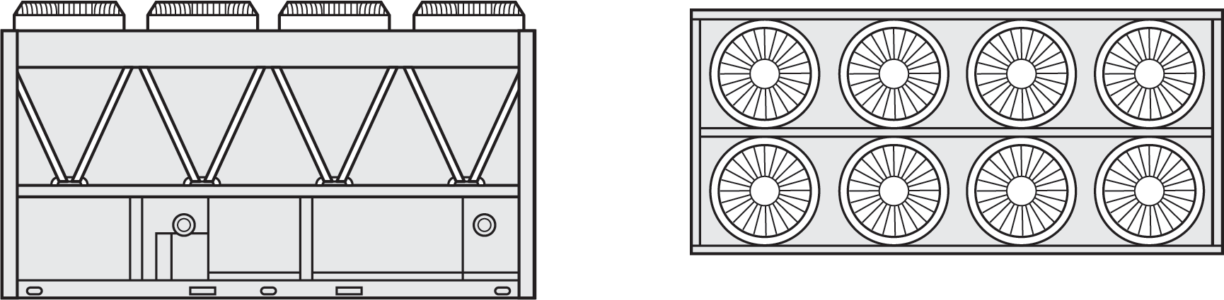
Air-cooled chillers function exactly the same as refrigerators, with the exception that an air-cooled chiller must be installed outdoors to be able to dissipate enough heat. The condenser has piping coils that the refrigerant flows through; these coils are attached to a network of fins that are usually made of aluminum. The fins greatly enlarge the surface area in contact with the air and increase the effectiveness of heat transfer to the air.
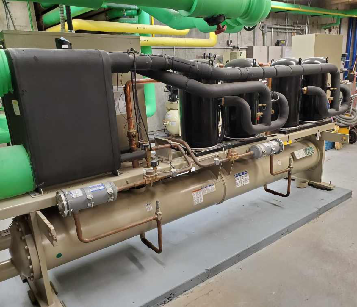
Water-cooled chillers use an extra piece of equipment called a cooling tower. A water-cooled chiller is normally installed indoors (Figure 26), which increases the expected lifespan of the chiller. Water, rather than air, is circulated over the condenser coils within a condenser heater exchanger, then pumped to a cooling tower, where heat is taken out of the water (called “condenser water”), then returned to the chiller condenser section. The chiller can be located inside buildings because the cooling tower does the heat transfer from the condenser water to the atmosphere and the cooling tower is located outdoors.
A cooling tower is simply another heat exchanger normally installed on the roof of the building or in a parking lot near the building, if the building is very tall. Parking lot locations are favoured because the noise and vibration caused by the cooling tower operation is not transferred to the building.
There are two different types of cooling towers: closed-circuit and open-circuit. Both types of towers serve the same purpose, but they cool the water in different ways.
A direct, open-circuit cooling tower is an enclosed structure that distributes the warm process water — in this case, condenser water (Figure 27) — over a labyrinth-like packing or fill, which provides an expanded air-water interface for heating the air and evaporating a portion of the condenser water. The condenser water is cooled as it falls through the fill and is then collected in a basin below. The heated moisture-laden air leaving the fill is discharged into the atmosphere, and the cooled process (condenser) water collected in the basin is returned to the chiller condenser to remove more heat.
Although open-circuit towers use an efficient, simple, and economical design, they expose condenser water to the atmosphere. All components in an open-circuit system, especially the chiller condenser section, must be compatible with the oxygen and other contaminants introduced via the cooling tower.
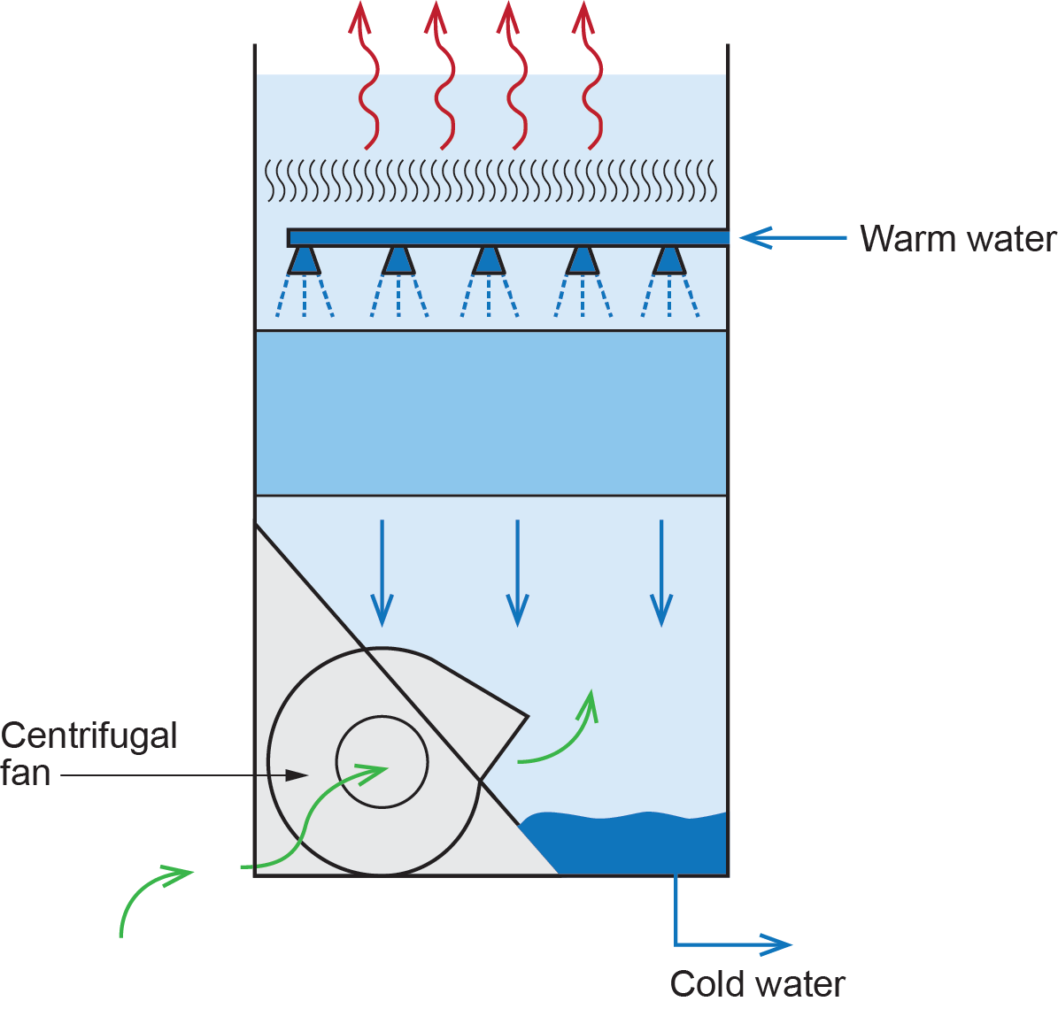
A closed-circuit cooling tower, or dry cooling tower, involves no contact between the air and the fluid being cooled (Figure 28). This type of tower has two separate fluid circuits: one where condenser water flows through a coil pipe located in a fan-forced air stream and the other where cool or cold water sprays into the air stream that flows around the condenser water coil. The air drawn through this cascading water spray provides evaporative cooling, similar to that in an open cooling tower, except that the condenser water never makes direct contact with the cooling air/water mixture. A closed-circuit cooling tower protects the quality of the condenser water, reduces system maintenance, and provides operational flexibility at a slightly higher initial cost than that of an open-circuit tower.

Heat Pumps
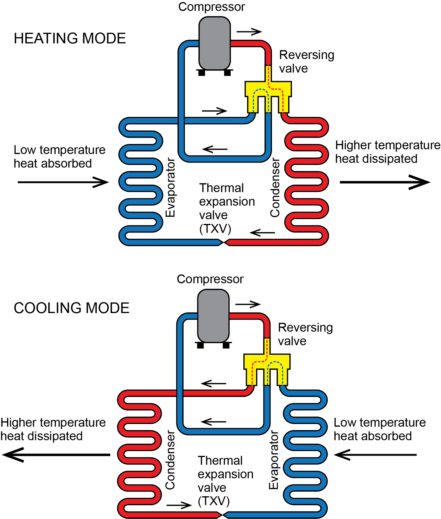
Heat pumps work on the same refrigeration cycle previously described with chillers. One significant difference is their ability to reverse the cycle using an electrically operated reversing valve, which can change the direction of the refrigerant flow. The reversing valve effectively swaps the functions of the condenser and evaporator making the heat pump either a heating or cooling source (Figure 29).
Heat pumps that extract low-temperature heat from the outside air and deliver higher-temperature heat through a forced-air distribution system, or vice versa, are relatively common in North America. When used to heat buildings, heat pumps can gather low-temperature heat from sources, such as outdoor air, groundwater, lakes or ponds, or tubing buried within the earth.
In a hydronic system using a heat pump as the heat source, the heat present in the refrigerant is transferred to the water that moves throughout the heating system. This is done through the compression cycle within the heat pump. The hot refrigerant leaving the compressor moves into a water-cooled condenser (Figure 30). The water within it absorbs the heat and carries it off to be used to heat the house and/or domestic water. Remember that the condenser and evaporators in a refrigeration system are simply heat exchangers. Hydronic systems, such as radiant systems that operate at low water temperatures, are always preferred from the standpoint of heat pump performance.
Air-To-Water Heat Pumps
Recent developments have made it possible to use air-source heat pumps in combination with hydronic distribution systems. Since these units use water as their means of heat delivery, they are classified as air-to-water heat pumps.
Air-to-water heat pumps (Figure 31) use the outside air as their source of heat. Even when it is very cold outside, the heat pump can extract heat from the air and move it into the building. The energy from the air is transferred via refrigerant to the water, which is then distributed through the piping. During the summer months, the system can work in reverse: cool water is run through the piping, absorbing heat as it goes.
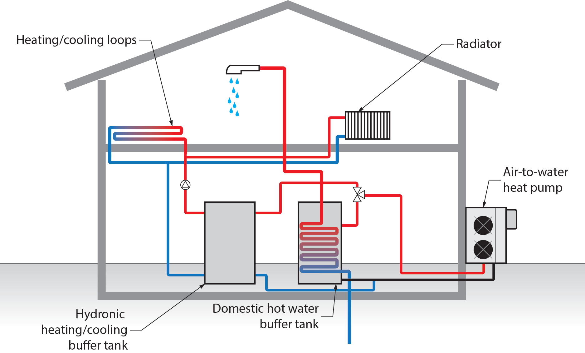
This water then goes back to the heat pump, where the refrigerant cycle removes the heat from the water by transferring it to the air outdoors. Note that if a heat pump uses the same open air heat transfer units to supply cooling water, they will require controls that monitor the dew point of the ambient air. This is necessary to avoid condensation forming on the cool surfaces of the heat transfer unit, which, in turn, promotes dampness and mould. This limits the minimum temperature of the cooling loop and cooling capacity of a radiant hydronic cooling system.
Water-To-Water Heat Pumps
A more fitting term for a water-to-water heat pump (Figure 32) would be a ground source heat pump, although the term geothermal is often extended to this type of system. A true geothermal system taps into heat emitted from underground hot springs, whereas a ground source heat pump conducts latent heat from below the surface of the earth.
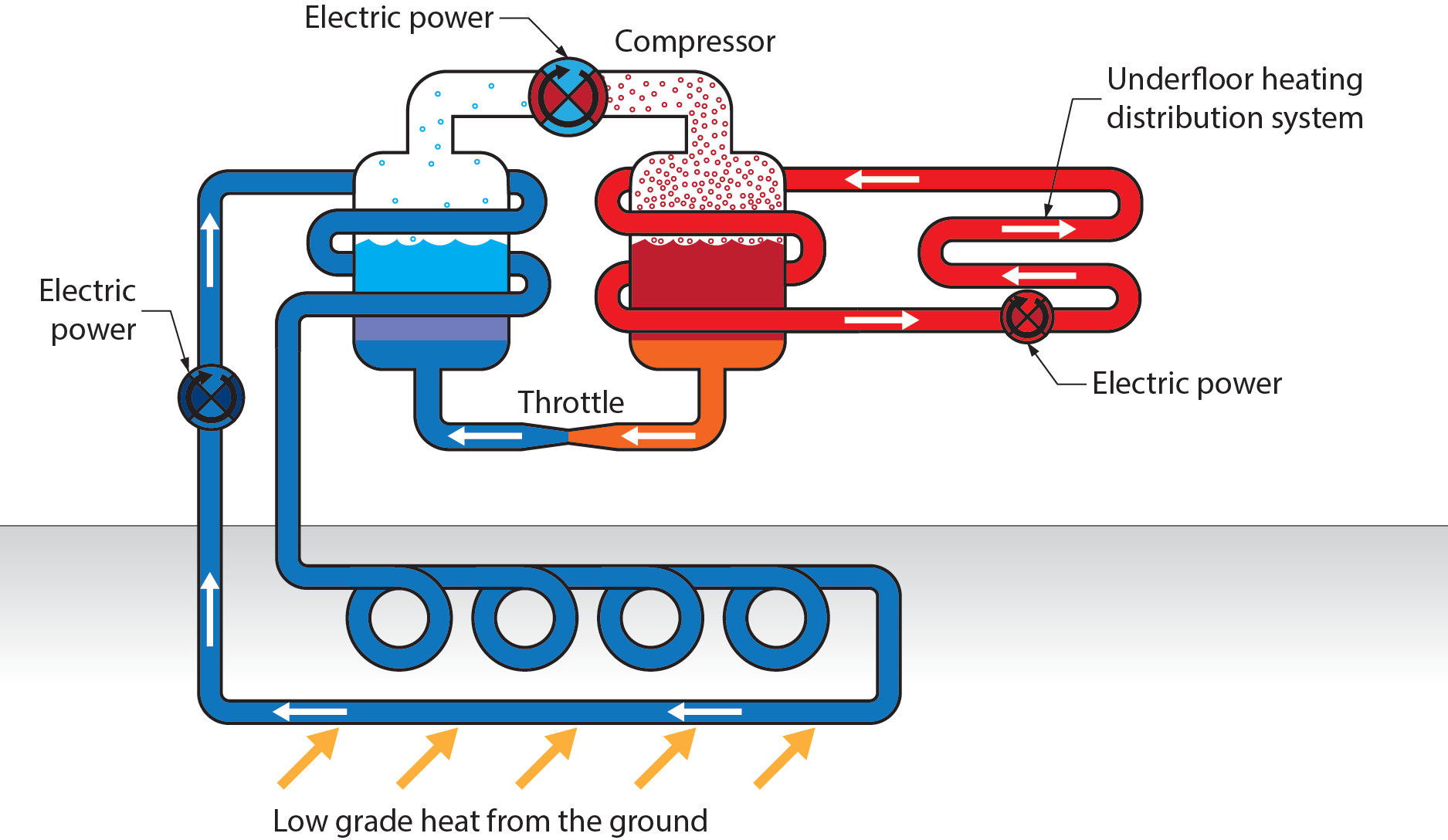
A closed-loop water-to-water heat pump has piping containing a heat-transfer solution, such as glycol or brine, running through the ground either vertically through a bored hole (if space is limited) or horizontally through trenches (e.g., on an acreage). The glycol or brine solution is the heat-transfer medium between the refrigeration cycle of the heat pump and the ground. In this case, the piping can be defined as a heat exchanger.
When the heat pump is in heating mode, heat from the ground is absorbed by the cool solution within the piping and transferred by the heat pump into the heating water for the building. Note that the fluids in the underground and in-house piping do not come into contact with each other; they are kept separated by the heat pump.
Similar to air-to-water heat pumps, the cooling cycle of water-to-water heat pump works in reverse. A reversing valve causes the refrigerant to move in a reverse direction within the heat pump, and heat is extracted from the building and deposited into the ground. These systems must be carefully sized and installed; the cost for installation is normally more than that for a conventional system, but they can easily cost even more to operate and maintain if not installed and sized correctly.
An open-loop system takes advantage of the heat retained in an available large body of water. The water is drawn from a well or pond directly to the heat pump. After extracting the heat, the system discharges the water back into the ground through a separate well or directly back into the pond.
Heat pumps are generally less costly to operate than any fossil-fuel-fired systems. In any properly designed heat pump system, the only operational energy cost should be the electricity needed to run the motors that power the pumps, compressors, and fans.
Heat Exchangers
Heat exchangers warrant mention because they come in various forms and can themselves be a source of heating or cooling. A heat exchanger is a device that transfers heat from one fluid to another without allowing the two fluids to make physical contact. Typically, both fluids in the system must be moving for heat exchange to take place. There are many types and styles of heat exchangers.
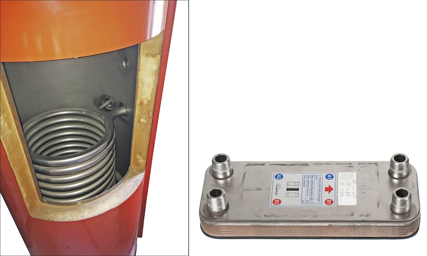
Water-To-Water Heat Exchanger
Water-to-water heat exchangers (Figures 33 and 34) are normally used to heat domestic water with a boiler but can also transfer heat between any two liquid mediums. Boiler water is sent into one side of the heat exchanger and transfers its heat to the coil surrounded by water within the tank. The boiler water and the water to be heated do not come in contact; instead, heat is transferred through the walls of the heat exchanger.
Heat exchangers are used to prevent mixing between potable water, like domestic hot water, and non-potable mediums, such as boiler water or a water/glycol mixture.
Watch the following video by Rinnai America Corporation (2021) on YouTube to see how Rinnai boilers work.
If you are using a printed copy, you can scan the QR code with your digital device to go directly to the video: How Rinnai I-Series Boilers Work
Air-To-Water Heat Exchanger
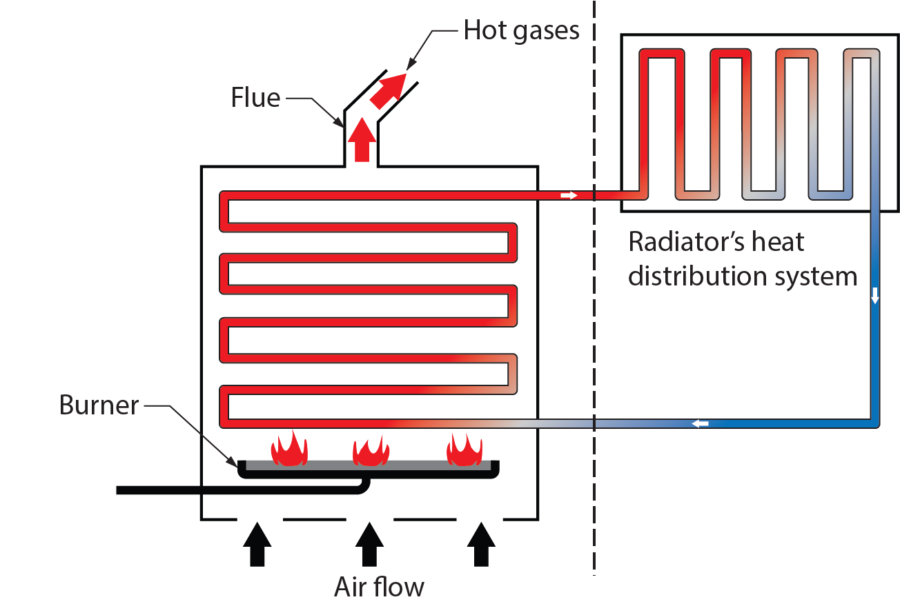
An example of an air-to-water heat exchanger would be the exchanger within a boiler, where water within steel or copper tubing or cast-iron sections is heated by hot flue gases produced by the burning of a hydrocarbon fuel, such as natural gas, propane, or fuel oil. The heat from the flue gases is transferred by conduction through the walls of the pipe or sections into the water, while the two mediums are kept separate.
Water-To-Air Heat Exchanger
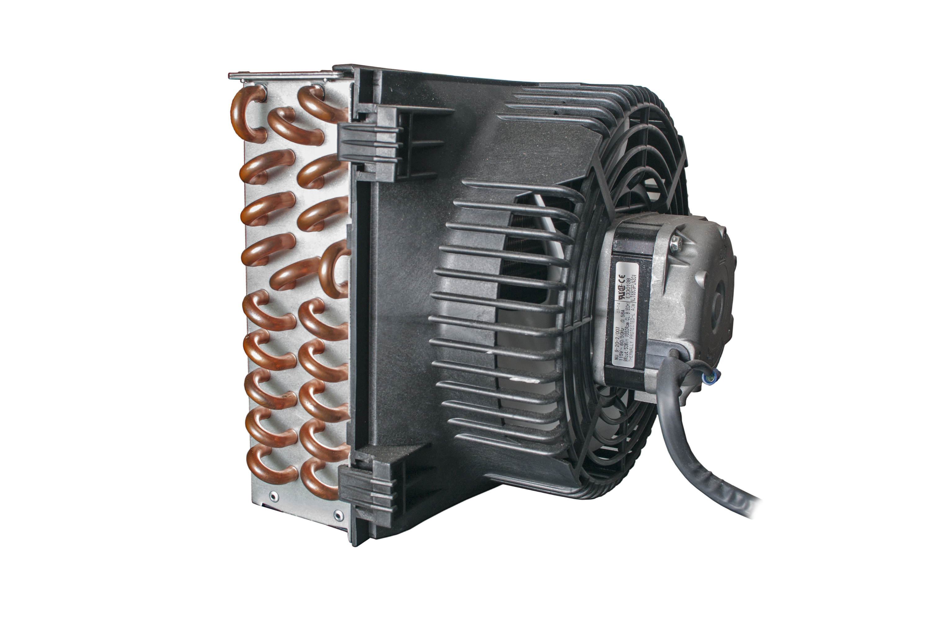
The heater emitters that release heat from the boiler water into the space being heated are examples of water-to-air heat exchangers. Figure 36 is a fan coil type where hot boiler water is piped to an exchanger, similar to a radiator in a car. An axial fan mounted behind the exchanger pushes air through the finned coils.
Air-To-Air Heat Exchanger
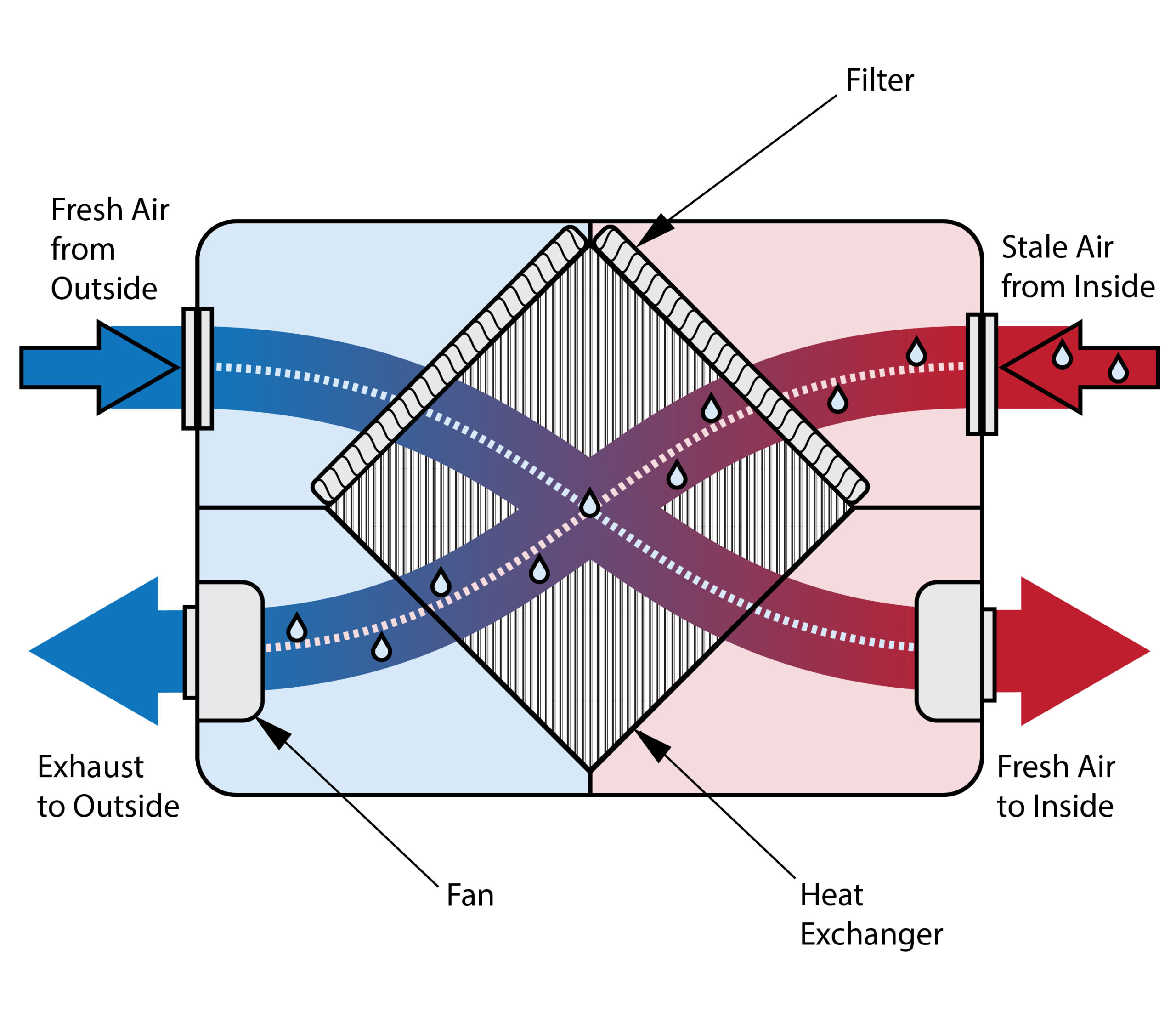
An example of air-to-air exchanger is a heat recovery ventilator (HRV). These are mandated by building codes for most new single-family house construction to get the necessary fresh air change. They can recover heat while exchanging stale indoor air with fresh outdoor air.
 Self-Test B-2.1: Heating and Cooling Sources
Complete the chapter Self-Test B-2.1 and check your answers.
If you are using a printed copy, please find Self-Test B-2.1 and Answer Key in the Appendix at the end. If you prefer, you can scan the QR code with your digital device to go directly to the interactive Self-Test.

References
HBW Closed circuit counter flow cooling tower [product diagram]. (2019). Jiangsu Huatal Cooling Technology Co., Ltd. https://www.htcoolingtower.com/hbw-closed-circuit-counter-flow-cooling-tower
Monadnock Cooling Systems Admin. (2017, July 10). Open circuit induced draft cooling tower [digital image]. In Cooling towers & their uses. Monadnock Cooling Systems, Inc. https://www.monadnockcooling.com/wp-content/uploads/2017/07/Screen-Shot-2017-07-10-at-2.22.39-PM.png
Rinnai America Corporation. (2021, March 2). How Rinnai I-Series boilers work [Video]. YouTube. https://youtu.be/TvCc3noYin4?si=w7KLhuqYTkqmMlrJ
Skilled Trades BC. (2021). Book 1: Fuel gas systems, heating and cooling systems. Plumber apprenticeship program level 2 book 1 Harmonized. Crown Publications: King’s Printer for British Columbia.
Trades Training BC. (2021). B-2: Describe hydronic heating and cooling generating equipment. In: Plumber Apprenticeship Program: Level 2. Industry Training Authority, BC.
VectorMine. (2023). Heat recovery ventilator as indoor hot air temperature usage outline diagram labeled educational physical principle for home ventilation system device for climate control economy vector illustration [Vector image]. Adobe Stock. Retrieved February 27, 2025, from https://stock.adobe.com/ca/images/heat-recovery-ventilator-as-indoor-hot-air-temperature-usage-outline-diagram-labeled-educational-physical-principle-for-home-ventilation-system-device-for-climate-control-economy-vector-illustration/461693074
Media Attributions
All figures are used with permission from Skilled Trades BC (2021) unless otherwise noted.
- Figure 2 Outdoor boiler with baffles visible by Frank Vincentz via Wikimedia Commons is used under a CC BY-SA 3.0
- Figure 4 Scotch marine two-pass fire-tube boiler from Steamboat.com (original image), was adapted by Skilled Trades BC (2021), and used with permission.
- Figure 5 Water-tube boiler by Jooja, via Wikimedia Commons, was previously adapted by Skilled Trades BC (2021), used under a CC BY-SA 4.0 license.
- Figure 11 is from TRU Open Press and can be used under a CC BY-NC-SA license.
- Figure 25 Open-circuit cooling tower (adapted for educational purposes under Fair Dealing guidelines), was from Skilled Trades (2021). The original image is from Monadnock Cooling Systems, Inc..
- Figure 26 Closed-circuit cooling tower (adapted for educational purposes under Fair Dealing guidelines), is from Skilled Trades (2021). The original image is from Jiangsu Huatal Cooling Technology Co., Ltd.
- Figure 34 Water-to-air heat exchanger is by Rod Lidstone and is used under a CC BY licence.
- Figure 36 HRV unit has been modified by TRU Open Press from original Heat Recovery Ventilator image from VectorMine (2023); found on Adobe Stock and used under the Adobe Stock Standard free trial license.
The job of the low-water cut-off is to shut off the burner should the water level fall to an unsafe level. The boiler manufacturer determines this level, but it is usually within one-half inch of the bottom of the gauge glass. (Section B-1.2 and Section B-2.1)
A device that measures and displays three different things at once: pressure, temperature, and altitude (or level) of a liquid in a system. It's commonly used in heating systems to monitor these conditions and ensure everything is working properly. (Section B-2.1)
A device used in heating systems to control the temperature of the water. It works like a thermostat but specifically for water, turning the boiler on or off to keep the water at the desired temperature. (Section B-2.1)
Boilers, depending upon their size, have one or more outlet tappings. The vertical steam piping from the tapped outlet joins a horizontal pipe called a header. The steam supply mains are connected to this header. If the boiler has more than one outlet, it is important to remember to pipe the headers with swing joints. This will help alleviate any stress on the boiler when the header heats up and expands. (Section B-1.2 and Section B-4.2)
Solar energy systems that consist of dark metal plates mounted on building walls or roofs. These plates absorb solar radiation, heating the air which is then circulated for heating purposes inside the building. They are a passive method of harnessing solar energy for space heating and ventilation. (Section B-2.1)
