B-1.3 Residential Forced Air Heating and Cooling Systems
In Canada, forced-air heating is the most common type of heating system used for residential and commercial buildings.
Pros and Cons of Forced Air Heating
One advantage forced-air systems have over other heating systems is the movement of the return air through a filter that constantly removes dust and other airborne particles from the air stream as the system works.
Air filtration is a feature that neither electric baseboard nor hot water (hydronic) heating systems contain. Filtering the air lessens the amount of dust and debris that settles on furniture or is breathed in by occupants and keeps debris from plugging heating and cooling coils.
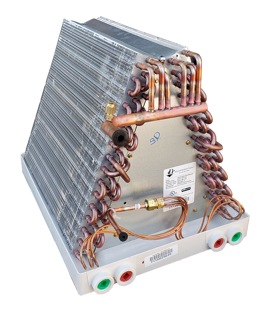
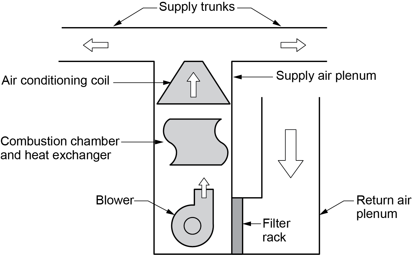
Another reason for the popularity of forced air heating systems is the ability to add an evaporator coil (Figure 2) into the ductwork so that the system can be used to cool the house in the summer months. This is another feature that neither electric baseboard nor hydronic systems can offer.
Forced-air systems are often chosen over hydronic heating systems because of the cost of installation. The cost of a ducted forced-air heating system is generally lower than a hydronic heating system.
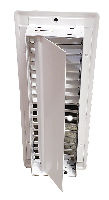
The downside of forced-air heating is the difficulty in maintaining a comfort level in all areas of the home. Typically, a single thermostat is located central to the structure, so it is not affected by cold transfer from outside walls and windows. The thermostat controls the on/off operation of the system. Airflow regulators, known as dampers, are installed in the individual supply duct runouts and/or the grilles and registers (Figure 3) to throttle airflow to a specific area. To maintain a consistent comfort level everywhere, the system must be balanced by adjusting each damper and measuring airflow at the outlets. Every adjustment has a direct effect on the airflow at other outlets, and any miscalculated movement of a damper’s setting will throw the entire system out of balance.
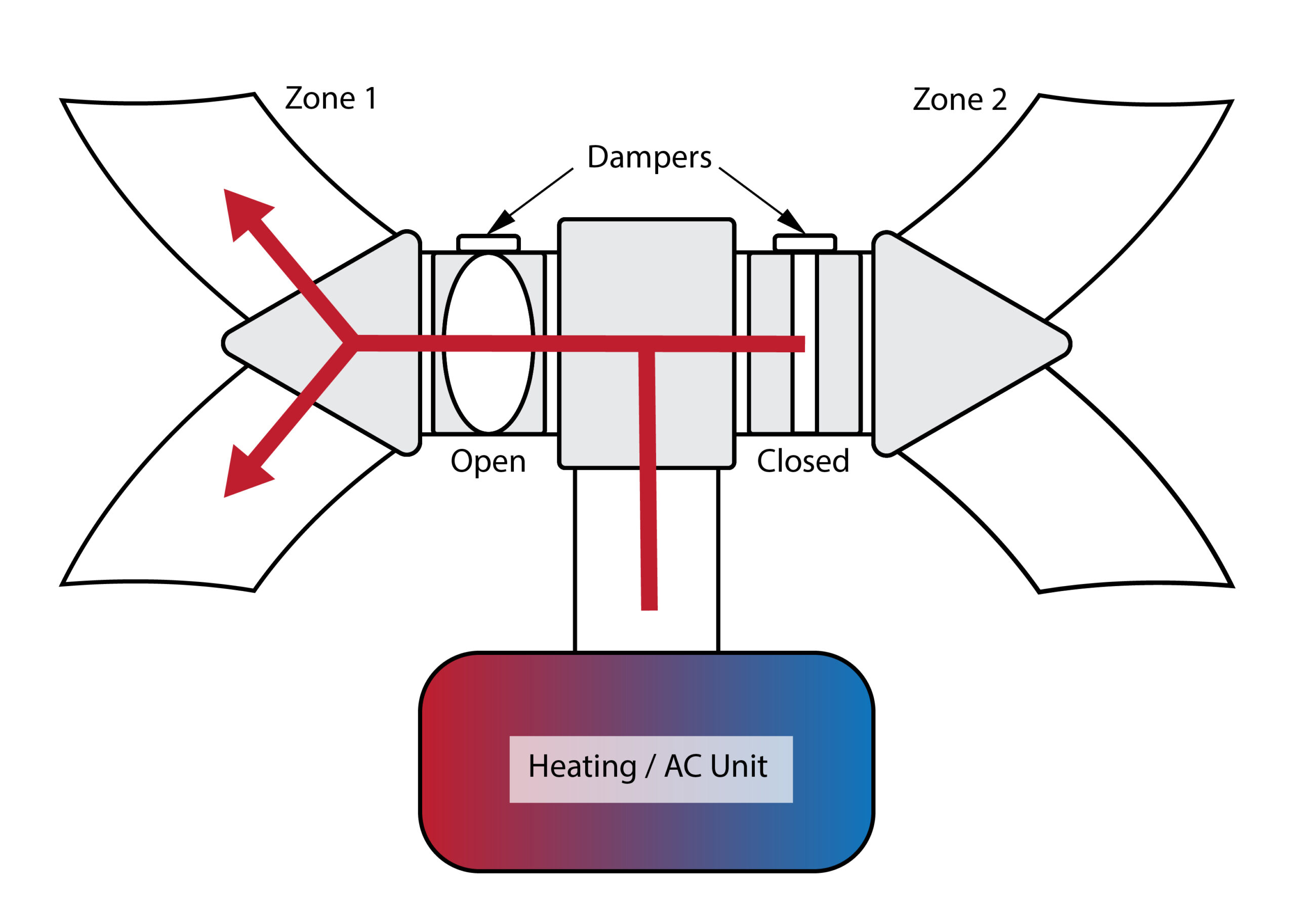
The air flow in individual rooms can be restricted by dampers in the floor grilles.
Furnace Types
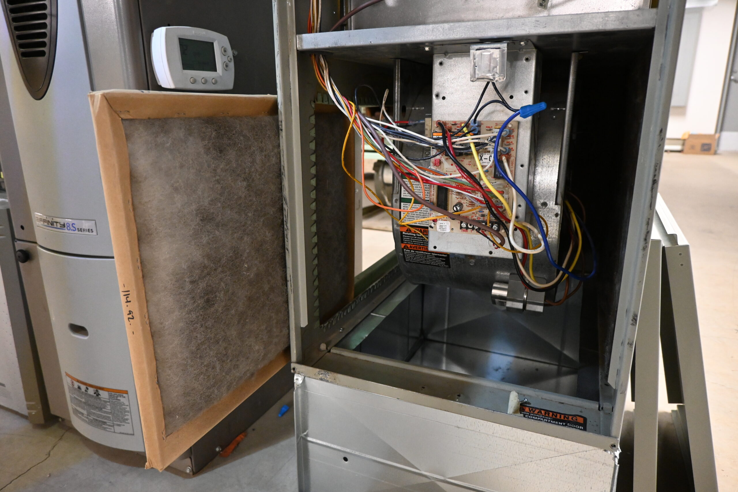
Regardless of type, all furnaces consist of an air filter, a blower, a heat exchanger/element/coil, various operating and limit controls, and two main air plenums (supply and return) for ductwork connections.
Efficiency Types
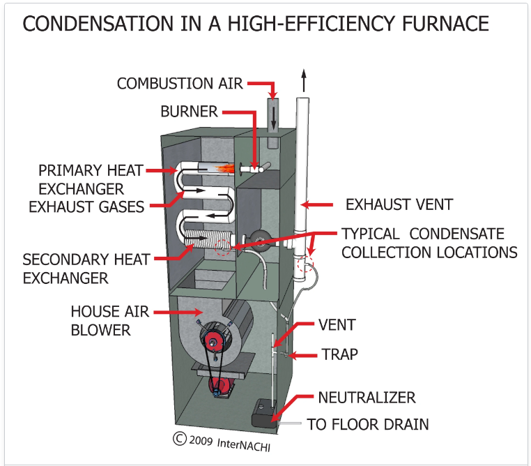
As of January 1, 2010, Canadian federal efficiency guidelines have determined that all new installations of residential furnaces must have a minimum annual fuel utilization efficiency (AFUE) of 90%. This means that new gas furnace installations must be of the condensing type. When more heat energy is taken out of the products of combustion to meet this new requirement, the water vapour within those products condenses back into water, which forms carbonic acid when mixed with the carbon dioxide in the flue gases. Depending on the drainage system and its overall dilution capabilities, this fluid may need to be drained directly (Figure 5) into an acid neutralizer.
Older (1980s–1990s) furnaces were considered mid-efficient, due to the design of the heat exchanger. These furnaces were capable of 80–83% efficiency. Very old furnaces (pre–1980) were known as standard efficiency, rarely breaking 78% efficiency.
Gas-fired furnaces are also split into categories based on their vent pressures and efficiencies (flue losses). Mid-efficiency furnaces are known as Category I and vented using metal Type B venting materials, whereas high-efficiency furnaces are Category IV and commonly use pressure sealed plastic Type BH venting materials.
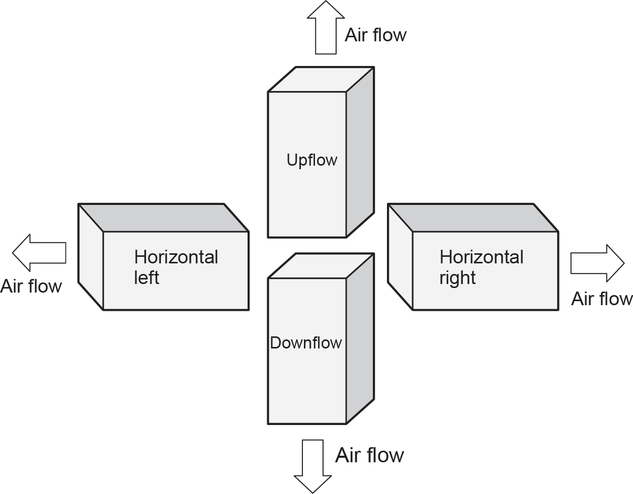
Air Flow Configurations
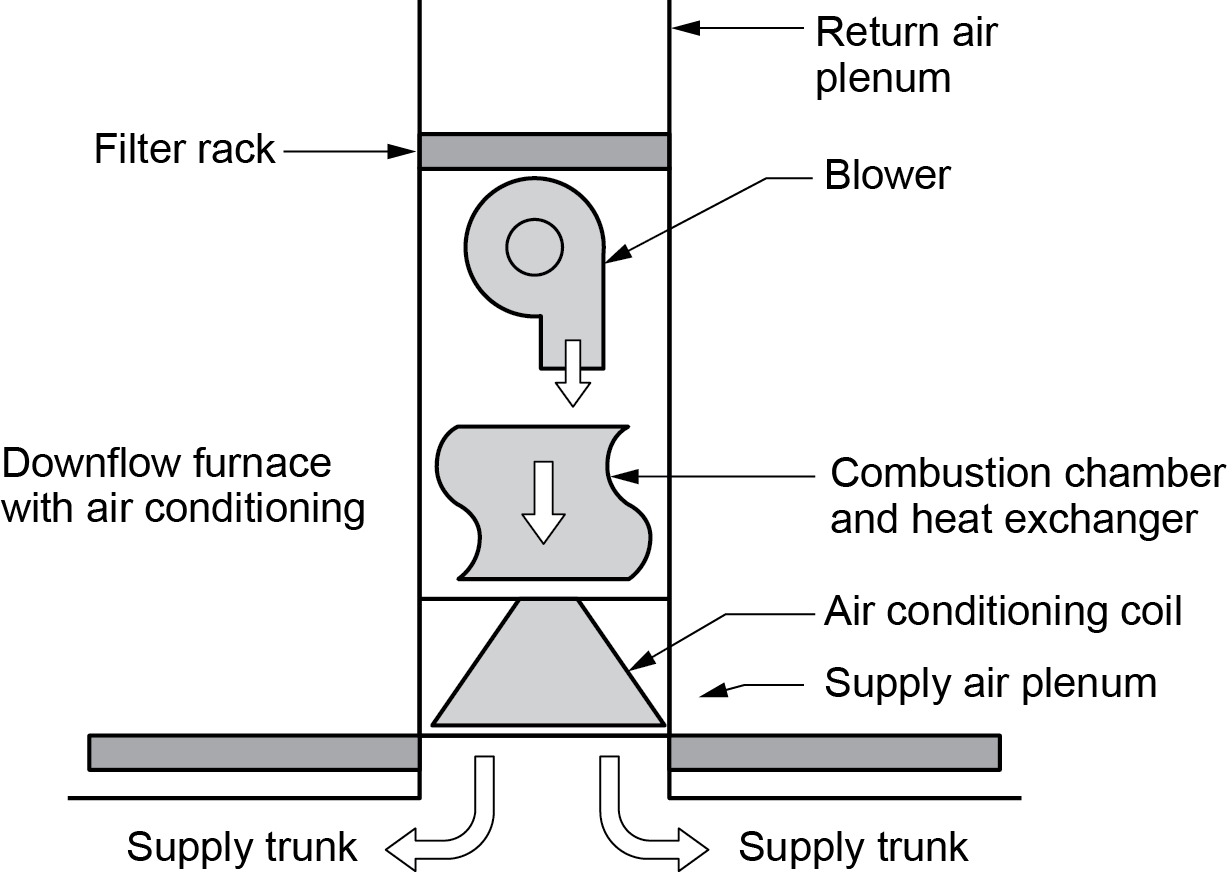
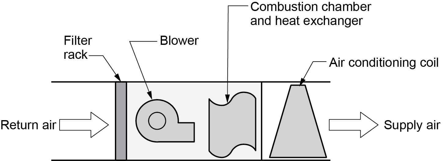
Because of their in-shot burner orientation, most mid- and high-efficiency furnaces can be installed as upflow (most common for multi-level homes) (Figure 6), downflow (for rancher-style construction with a crawl space) (Figure 7), or horizontal flow (for mounting in a crawl space or attic) (Figure 8). These are known as convertible or multi-position furnaces (Figure 9). A convertible gas furnace may require special vent and drainage modifications to accommodate the various configurations.
Air Filters
All forced-air furnaces require air filtration to operate safely and efficiently. Some furnaces are intended for use with specific types of filters, but in many cases, the filter is an add-on component, so the appropriate filter must be chosen.
Airborne particles can include dust created by activities both inside and outside the house, hair and skin flakes from pets and humans, tobacco smoke, spores, bacteria, and viruses. Some filters will easily remove the larger particles, such as visible dust, but smaller particles that can enter the lungs, such as bacteria and viruses, are the most problematic. For these particles, the chosen filter must have the ability to remove such small particles.
The minimum efficiency reporting value (MERV) is a numerical value given to filters to identify their filtering ability. This industry standard operates on a numerical value between one and 16 microns, with higher numbers indicating greater filtering capacity.
High-efficiency particulate arrestance (HEPA) filters, which remove a very high percentage of airborne contaminants, are often specified for various commercial, industrial, and institutional applications.
The tighter the filter media’s fabrication, the harder it will be for airflow to pass through it. The blower fan’s power and volume capabilities will need to be assessed for compatibility with each filter type.
Filter Types
The three basic types of air filters are media, electrostatic, and electronic.
Media filters (Figure 10) are the least complicated and, therefore, the least costly and most-used type. Made from paper, fibreglass, or cloth, they are positioned in the return air stream, where air is pulled through them toward the blower. They have a hammock, slab, or pleated design; can be reusable or disposable; and are available as low-, medium-, and high-efficiency types.

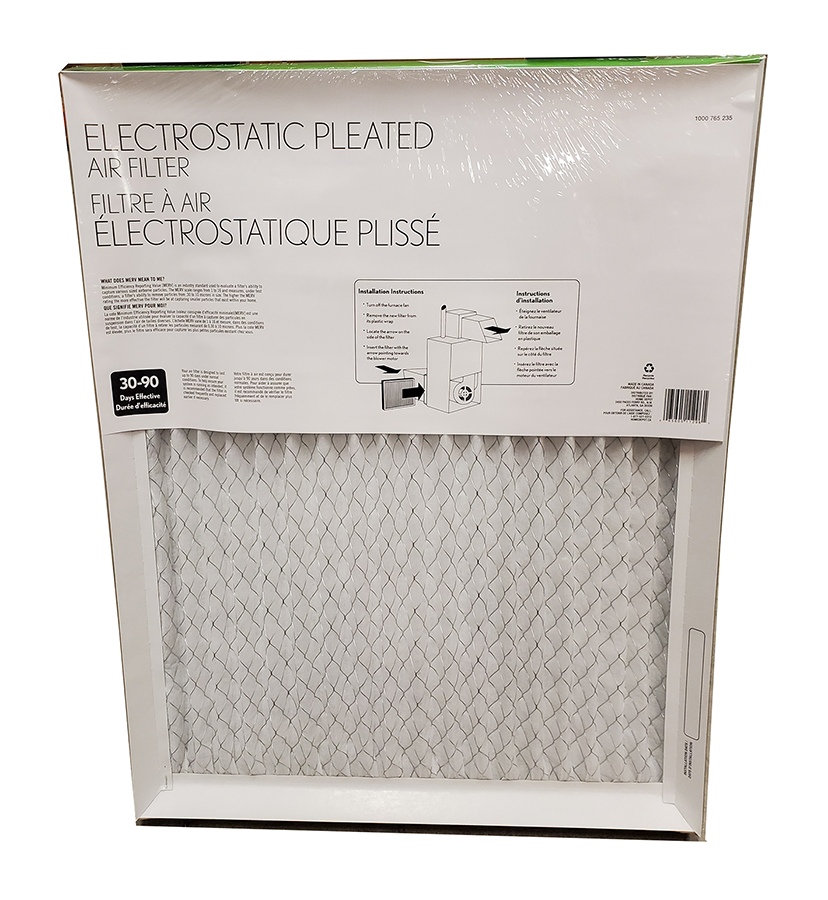
Electrostatic filters (Figure 11) are media-type filters made from a material that generates a static charge when air flows through it. This static charge attracts and holds more particles to the medium than regular media filters.
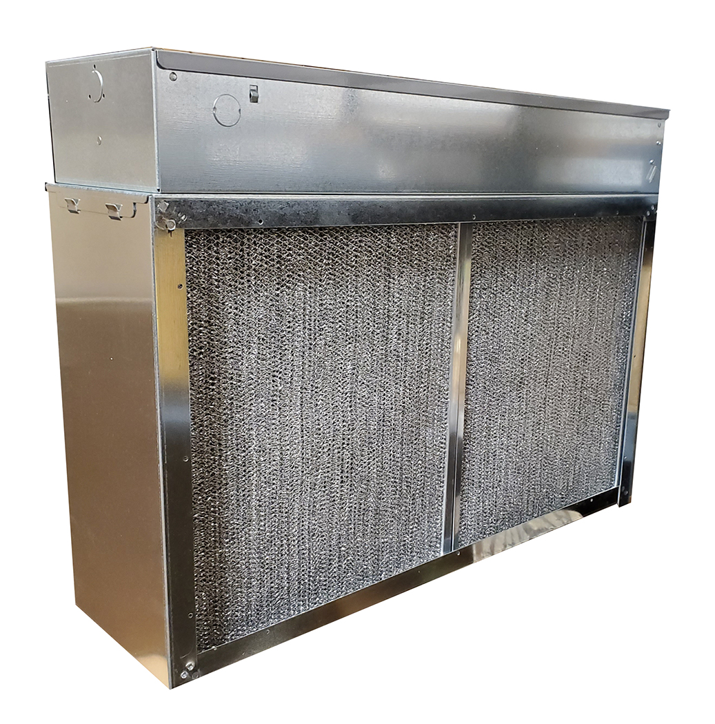
Electronic air cleaners (EAC) use an electronic charge to remove and collect particulate from the circulated air (Figure 12). They use an external power source rather than the airflow itself to generate the charge that attracts the particles. A charged plate collects the particles and requires manual cleaning.
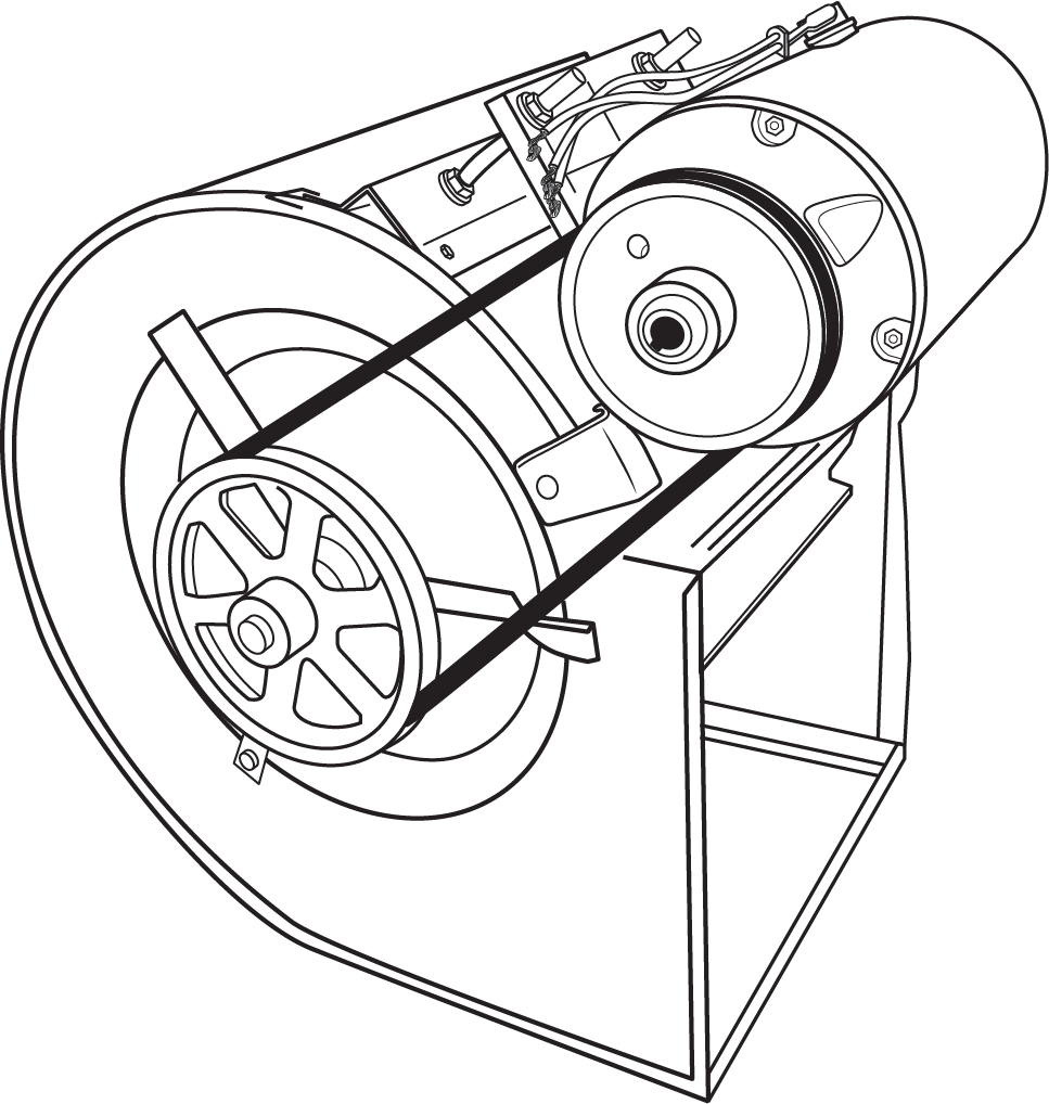
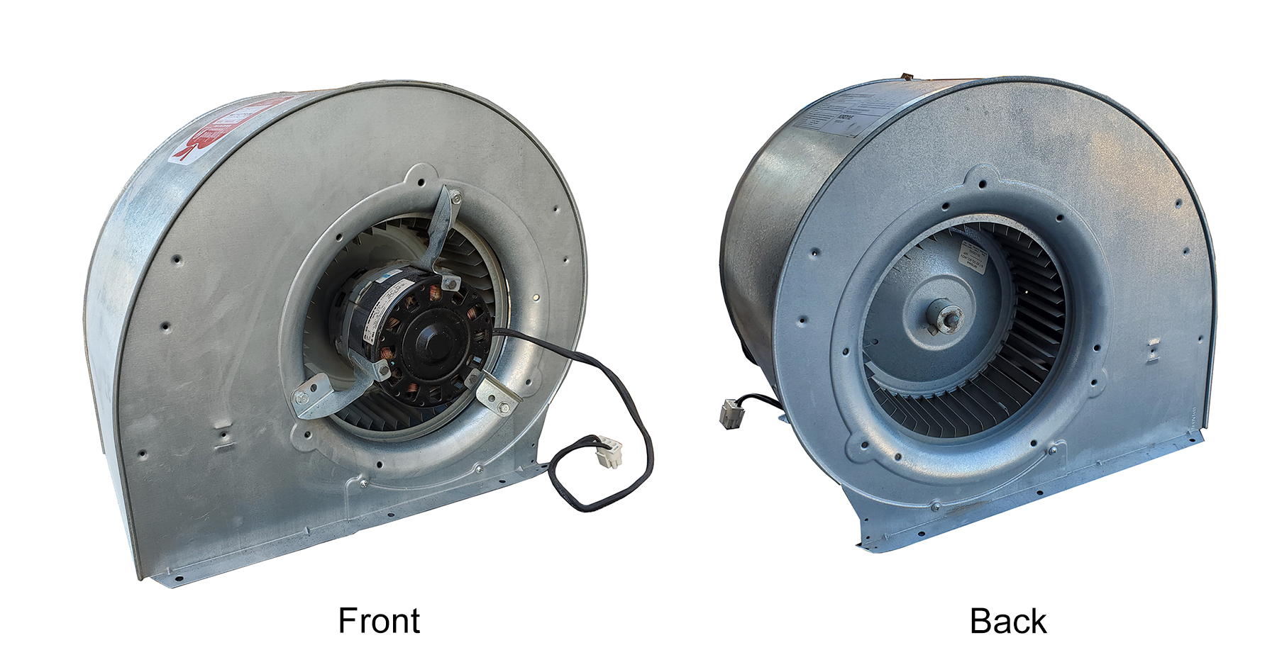
Blowers
The blower is a squirrel-cage-type fan positioned between the filter and the heat exchanger. Air is pulled through the filter and pushed across the heat exchanger into the main supply plenum. Older models were driven by a belt connected by pulleys or sheaves to an alternating current (AC) single-speed electric motor (Figure 13). The speed of the blower could be increased or decreased by altering the position of the belt within an adjustable pulley mounted on the motor’s shaft. Blowers can still be found today in appliances, such as rooftop heating and cooling units, which can be built larger to accommodate the extra room needed for the fan and motor.
Modern blowers (Figure 14) do not use pulleys and belts. The motor is mounted within the fan housing and connected directly to the fan’s drive shaft direct drive. The speed of the fan is adjusted by connecting one of the wires from the motor’s speed taps to the power supply.
Some high-efficiency blower models use direct current (DC) direct-drive motors capable of automatically adjusting their speed in relation to the filter’s airflow. As the filter starts to collect dust, air flow through it is restricted, and the blower ramps up its speed to maintain the required air flow.
Heat Exchangers
Forced-air furnace energy sources are gas (natural or propane), fuel oil, electricity, heat pump, or hydronic (hot water) coil.
Gas or Fuel Oil Furnace
- Heat is produced by combustion of fuel gas through a burner or oil-type burner located in a combustion chamber.
- A heat exchanger keeps the products of combustion separated from the supply air stream.
- Ignition is provided by an electric spark, standing pilot, or hot surface igniter.
- There is a delay between the burner ignition and blower operation so that cold air is not blown into heating spaces before the heat exchanger has reached temperature.
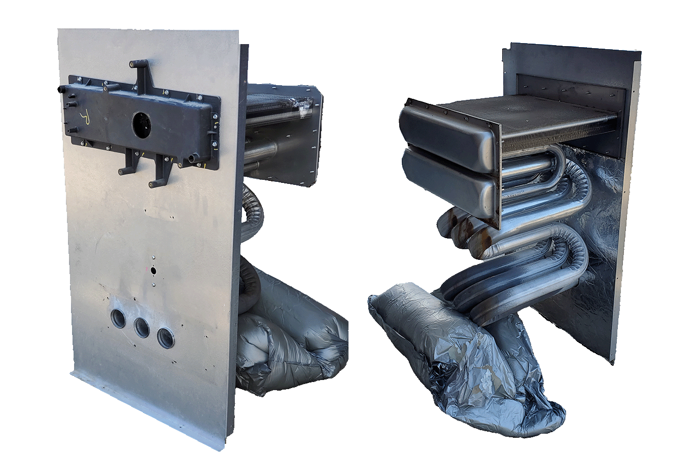
- High-efficiency gas furnaces have a secondary heat exchanger to absorb as much heat as possible from the products of combustion and, thus, release flue gas condensate that must be drained to a safe location (Figure 15).
- Safety devices ensure that combustion gases and unburned fuel do not accumulate in the event of an ignition or venting failure.
Electric Furnace
- Heating elements installed in the air stream are used to heat the supply air.
- When the thermostat calls for heat, the blower and electric element(s) come on at the same time.
- When the thermostat is “satisfied,” the blower and element(s) shut off.
- It has no heat exchanger, minimal moving parts, and requires very little maintenance.
- It is usually more expensive to operate than a natural gas furnace.
Heat Pump
- A heat pump extracts heat from the environment, using either the ground or outside air as the source, via the refrigeration cycle.
- It requires less energy than electric heat and is normally more efficient than fossil-fuel-fired furnaces (gas/oil).
- Air-source types may not be suitable for cold climates unless used with a backup (secondary) source of heat. Newer models may still provide heat when installed in temperatures below 0°C (32°F).
- A refrigerant coil is installed in place of the burner/heat exchanger. The system can also be used for cooling in a central air-conditioning system.

Hydronic Coil
- A hydronic coil combines a hydronic (hot water) heat source with forced-air delivery.
- Heat is produced by the combustion of fuel (natural gas, propane, wood) or electric heating elements in a hot water boiler.
- A heat exchanger, in the form of a hydronic coil, is placed in the air stream of the air handler. Copper is often used in the construction of supply and return manifolds and tube coils.
- Heated water is pumped through the heat exchanger then back to the boiler to be reheated. The air stream picks up the heat from the hot water coil and distributes it through the duct system.
- With a wood-fired boiler, a buffer tank is used between the hydronic coil and the boiler to store the energy. This enables the wood boiler to fire continuously while loaded with wood and the hot water to circulate intermittently as space heating is required.
Duct Systems
Ducting is normally made of galvanized sheet metal or aluminum. It can be formed into square or rectangular ducts with machines or purchased in two L-shaped pieces and snapped together on site. Round ducts are also available in the same configuration and material and can be purchased in snap-together pieces or continuously formed lengths known as “spiral.”
Warm air is moved by the blower through the supply air plenum into the trunk duct and distributed into the branches connected to the supply grilles or registers.
The plenum is the duct that connects directly to the furnace. There is a supply plenum and a return plenum on each forced-air furnace. The air filter is always mounted either inside the blower compartment or onto the return air plenum, where it attaches to the furnace.
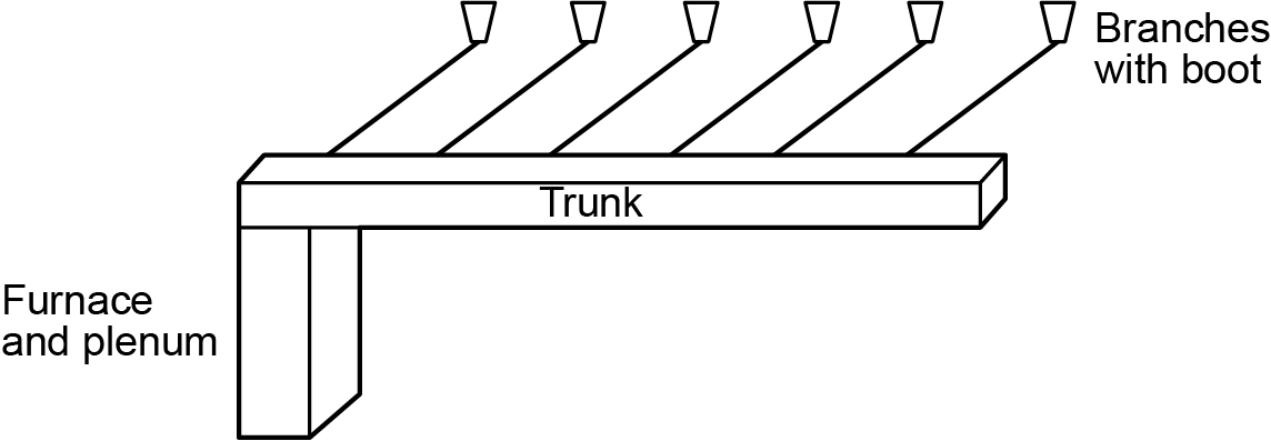
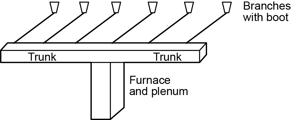
If the plenum directs air into a trunk that runs in one direction only, away from the furnace, it is a one-way trunk and branch system (Figure 17). Such a system might result from the furnace being located near one side of a structure. A furnace located near the middle of the structure has two or more trunks running in each direction and is therefore called a two-way trunk and branch system (Figure 18).
Branches are ducts connected to the trunk main and terminating at the boot, which holds the heat grille or register in the floor, wall, or ceiling.
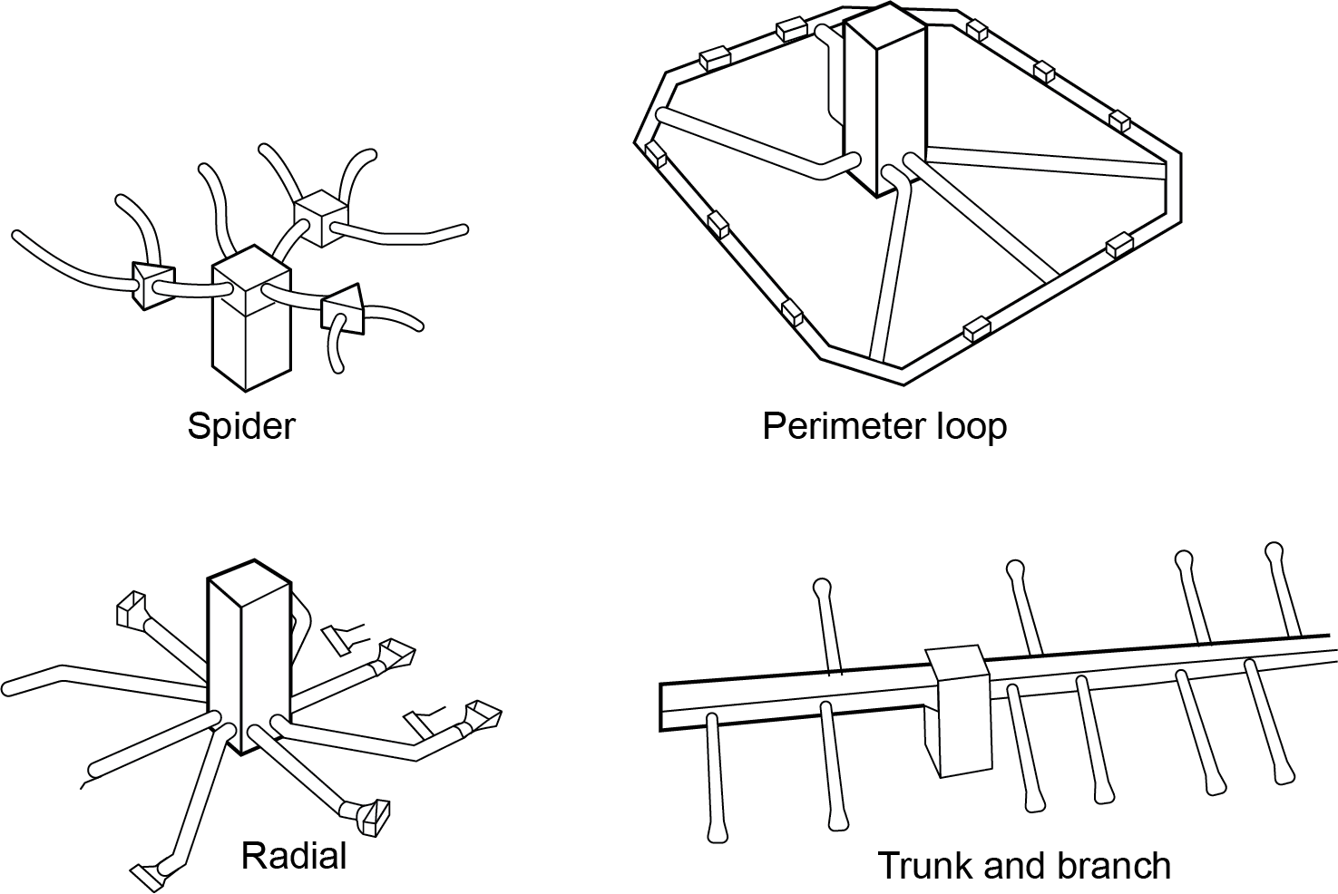
In addition to the trunk and branch layout, branches can be installed in a spider, radial, or perimeter loop configuration (Figure 19).
A branch that connects to a terminal fitting on an exterior wall will allow outside air to be drawn into the return air system whenever the blower operates. This is installed so that fresh air for the ventilation of the building and health of its occupants can be heated and distributed throughout the building.
Airflow Controls
Most duct systems in residential applications have manually adjusted dampers to control the airflow to the heat registers. The initial commissioning balancing process sets and locks these dampers into place. When the heating system operates, warm air is delivered evenly to all areas of the structure. If a demand for heat exists in selected areas only, a more sophisticated system of control is required, known as “zoning.” This involves installing motorized dampers on either the trunk or branches that open or close in response to an electric circuit being energized. For instance, in a two-storey home with a suite in the basement, one dedicated trunk could supply heat to the basement branches only while the other supplies the upstairs branches. A large motorized damper on each trunk would allow someone to control the heat supply to either the upstairs or the basement independently or simultaneously. Motorized dampers are not normally found in residential buildings.
Forced-Air Add-On Devices
Outdoor air in the winter can become very dry. Moisture levels are reduced with a drop in temperature. A humidifier maintains indoor relative humidity to around 40%. Moist air helps maintain comfort. Excessively dry air can make occupants feel colder than normal.
Benefits of Humidifiers
- Assists in minimizing the presence of static electricity.
- Helps keep nasal membranes from drying out (dry nasal membranes reduce occupants’ susceptibility to fight colds and other airborne viruses).
- Prevents certain building materials from drying out, such as hardwood floors.
There are many types of humidifiers available, with each type introducing water vapour into the supply air stream in various ways. A control called a humidistat measures indoor humidity and activates an atomizing or steam type humidifier installed onto or inside the supply air plenum.
Controls
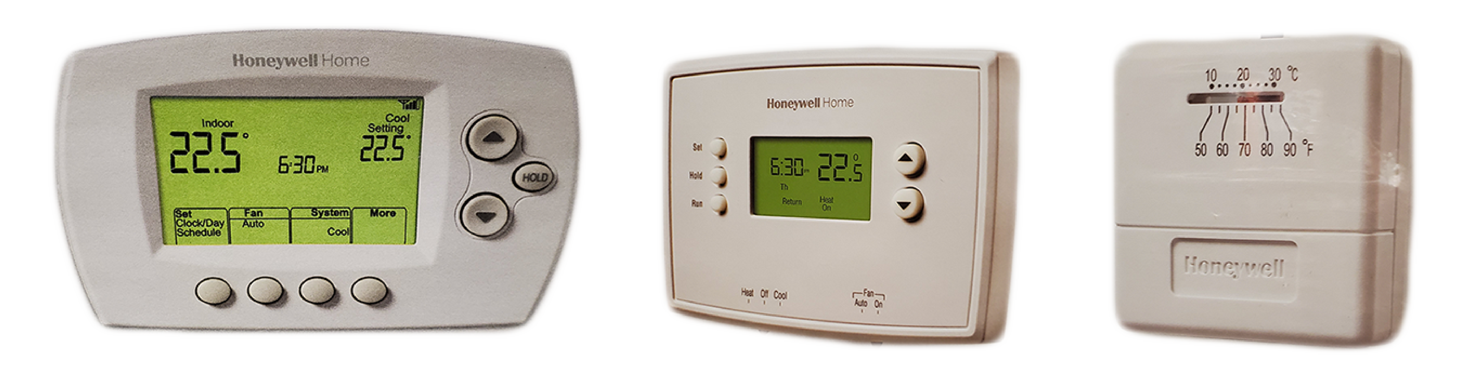
The main comfort control for a forced-air system is the thermostat. It is mounted on an interior wall, usually central to the floor area on the main living floor. It is installed around 1.5 m (5 ft) above the finished floor level in an area where it will not be exposed to stray heating or cooling effects. Older-style thermostats contain an internal bimetal coil that, when exposed to a change in temperature, rotate and make or break a set of electrical contacts to activate or deactivate a heating system. Newer-style thermostats use thermistors to sense the temperature in the structure. Most thermostats, as well as the other controls on a heating system, operate on a 24-volt AC-control voltage.
Thermostats can be heat-only, heat/cool, analogue, digital, digital/programmable, or Wi-Fi–enabled (“smart”). Programmable thermostats are increasingly popular with forced-air heating due to the air’s low thermal mass. This means the temperature settings on a thermostat serving a building heated with forced air can be set to a lower temperature in the evening or anytime the building is unoccupied, then raised quickly during occupied hours. “Smart” thermostats communicate through the customer’s Wi-Fi system and can be adjusted remotely for even more control options.
Other controls found on gas-fired furnaces include:
- High temperature limit switches that open an electrical circuit and shut off the gas valve when it senses excessive temperature inside the heat exchanger.
- Flame rollout switches that open an electrical circuit to shut off the gas supply if the flame rolls off the burners and into the appliance’s controls compartment.
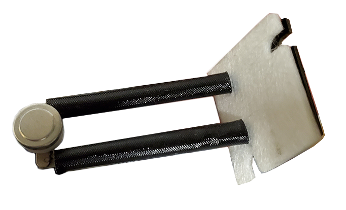
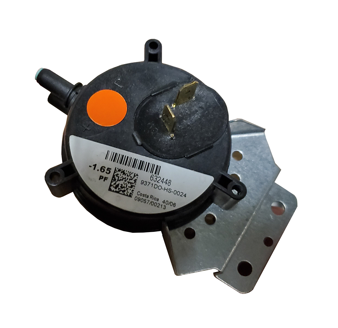
- Air pressure switches (Figure 23) that are set to sense designed pressures within the combustion chamber, vent piping, or combustion air intake piping and that open or close electrical contacts when it senses pressures above or below the required designed pressure.
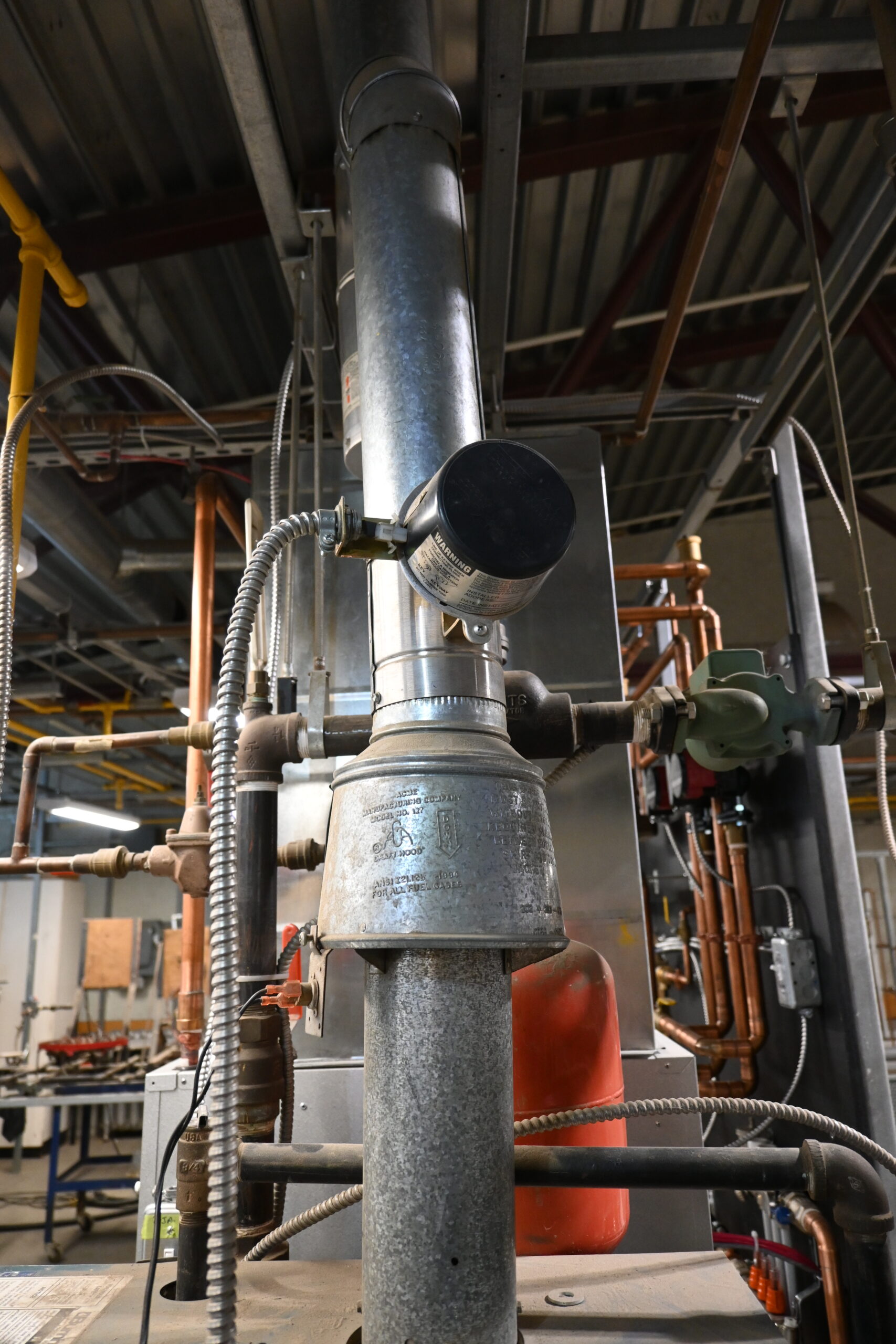
- Blocked vent safety switches located on the draft hood of older appliances that sense the heat from a blocked venting system above the draft hood and open electrical contacts to shut off the burner.
- Gas pressure regulators that control the pressure of gas supplied to the burner and in the piping that feeds heating equipment.
- A furnace control module that controls the operation of the gas delivery system. Newer modules, called integrated furnace controls, also control the blower.
 Self-Test B-1.3: Residential Forced Air Heating and Cooling Systems
Complete Self-Test B-1.3 and check your answers.
If you are using a printed copy, please find Self-Test B-1.3 and Answer Key at the end of this section. If you prefer, you can scan the QR code with your digital device to go directly to the interactive Self-Test.

References
Freitas, T. (2024, August 22). Locating Your HVAC dampers [image] in “How to find dampers in ducts”. Angi.com. Retrieved February 27, 2025, from https://www.angi.com/articles/how-to-find-dampers-in-ducts.htm
Skilled Trades BC. (2021). Book 1: Fuel gas systems, heating and cooling systems. Plumber apprenticeship program level 2 book 1 (Harmonized). Crown Publications: King’s Printer for British Columbia.
Trades Training BC. (2021). B-1: Describe types of heating and cooling systems. In: Plumber Apprenticeship Program: Level 2. Industry Training Authority, BC.
Media Attributions
All figures are used with permission from Skilled Trades BC (2021) unless otherwise noted.
- Figure 1 Force air furnace media filter installation is by TRU Open Press.
- Figure 3 Supply duct dampers is by TRU Open Press, modified from original image by Angi (2024) for educational purposes.
- Figure 5 High efficiency gas furnace with condensate drain going to an acid neutralizer is ©InterNACHI® and is used with Permission.
